Motivation
From all Science Fiction movies, what is the most iconic item?
For me, the Flux Capacitor from "Back to the Future" ranks pretty high, but it is still topped by the HAL9000 computer from Stanley Kubrick’s “2001: A Space Odyssey”. I love this, and I built one. It took me some time to post the results - but here they are.
When surfing the web, one finds many places where people have built the main panel with the red eye, the speaker grille, and the “HAL9000” decal. I tried to go a little beyond that, as I wanted my HAL to have further functionality. The coolest thing would have been to build that whole wall with two sets of four monitors on each side...
...but that was beyond my scope/available space/budget.
I tried to recreate something more along the lines of the pod bay, where the HAL panel appears on the right side, next to a monitor.
My goal was to build a pretty good replica of the HAL panel, and then take some freedom and mount this on a bigger plate that features a few displays and input devices (buttons, joystick). The whole device is operated by an Arduino and a Raspberry Pi.
The first step was, of course, building the main HAL panel. On the web, I found some really nice inspirations. Great research has been made in a contribution at
www.therpf.com and
another thread on that site has some additional resources on the measurements. The most important single detail is, of course, the eye. As discussed in the two links above, the original HAL features a rare Nikkor fish-eye 1:8 f=8mm lens which is beyond my budget, and which is not easy to replicate. Then, I found an
article at adafruit.com in which they build a HAL replica, using a 4-inch Arcade button which looks very close to HAL’s eye. And this is what got me started!
In the Adfafruit article, they mention the 80/20 Rule (that 80% of a result stem from 20% of the effort). In that spirit, I did not plan to go the extra mile to achieve a 100% replica, but I was happy at the 97% level, if it allowed me to stay on a budget below $100.-. If, at the first glimpse, people are not able to distinguish my HAL from the original, this is good enough for me. I do not have access to tools for working with metal or aluminum. So, my HAL is made of wood – and it uses the arcade button for the eye, although with some improvements, as compared to the adafruit.com article.
The very first step, was to come up with the dimensions for the face plate. In the articles at therpf.com and other sources on the web you can find slightly different values. The following dimensions are what I decided to use for the panel.
HAL Eye and Speaker Grille
For the construction of HAL’s eye, I followed closely the instructions from
adafruit but added two important details. The HAL eye from adafruit is too red as compared to the original and it lacks the inner details of the Nikon fisheye lens. This is easy to improve.
I started disassembling the button as described on the adafruit page,
but I also removed the red piece from its white background and removed the transparent red screen. The latter is replaced by a piece of black cardboard with a small hole inside.
The perfect size of the hole is that from a hole punch (actually, I started with a larger hole, but fixed that later). On this, I glued a glass marble (one with a flat back side) which looks like the inner lens from the fisheye lens.
A white flashlight behind this construction gave a first idea what the final result would look like. The darker look is much closer to the original HAL (the marble is not really visible in this picture – it looks better in real life).
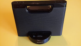
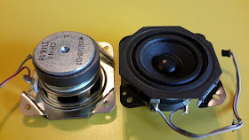
The second important ingredient for the front plate is the speaker grille. It took me a few visits to different thrift stores to find something that was suited for this. Finally, for $3.50, I found a used SONY iPhone dock from which I extracted the speakers and the grille.
With a metal saw I cut the grille to the required shape for the HAL face plate.
HAL Faceplate
The faceplate is made of 1/4″ plywood and 1/8″ x 1/2″ bass wood for the frame. It has openings for the 100mm push button (the eye), a speaker, a microphone, and slits for mounting the speaker grille.
The bottom piece, the speaker grille, and the bezel of the push button are painted using a metallic-looking spray paint. We are using the paint that was recommended on the adafruit page and it worked very well for the metal speaker grille, the wooden frame, and plastic bezel. Before spraying, we covered the inside of the bezel with painters tape, to keep it black.
Then I spray painted the upper front piece flat black.
And here are the results:
The last missing item for the faceplate is the “HAL 9000” decal. For this, I used the image that is posted at http://goldenarmor.com/hal9000.

This is the final face plate:
Building the Enclosure
In order to have a “full” computer, I decided to put the faceplate into an enclosure which is roughly the size of the smaller computr desk in the POD bay room.
However, instead of a single bigger monitor, I oped for a number of different input/output elements, including push buttons, a joystick, an infrared motion sensor, four different LED and LCD displays, and a webcam.
These are the elements that I’m using:
- Input: three blue quadratic push buttons; one white push button; a joystick; a infrared motion sensor (PIR); a web cam.
- Output: a 4-digit 7-segment LED display; a 1602 LCD display (2 rows with 16 characters each); a 2.2″ TFT LCD screen (240×320); and a 4.3″ TFT LCD monitor (sold cheaply as “rear view monitors” for back-up cameras).
In addition, my unit will also house a temperature sensor (DHT22), a clock, a mp3/wav player (DFPlayer Mini). The brains are an Arduino Mega, to deal with the input/output – and a Raspberry Pi, to deal with the web cam and the 4.3″ monitor.
Here is a sketch of the case that will be housing my HAL 9000.
And here are the first steps towards building the box.
And this is a first look at where the elements will sit.
Using a flat black paint, the case is then painted black and wooden pieces are glued to inside for mounting the hardware.
The last image shows the first elements mounted: the faceplate (speaker and 100mm push button are visible), the 1602 LCD display (top, green PCB), the PIR (below the green PCB), the four push buttons (bottom, middle to right), the joystick (above the left push button), the 2.2″ TFT LCD (red PCB), and the 4-digit/7-segment display (right, blue PCB). The Arduino Mega and the Raspberry Pi are placed where they will later be mounted.
The HAL 9000 Logo
A major step is when HAL gets its name. I found a nice version of the HAL 9000 logo on the web. In scribus, I adjusted the size, so I could have it printed as a 6×4 photo. I included four versions which differ by a few percent in size, just in case that the printer does not print it exactly in original size. Below is the final version which prints at 300dpi for a 6×4 photo. This was glued to the face plate using some white glue.
Web Cam and 4.3" LCD Monitor
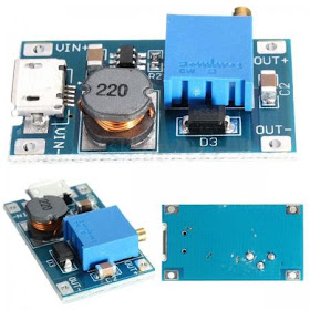
Now let's look at the electronics. Initially, the Raspberry Pi will operate the webcam and the 4.3″ TFT (rear view monitor) screen, while everything else will be connected to the Arduino Mega. The 4.3″ TFT screen is made to operate at 12V. Intrinsically, it is actually operating at 5V, but it includes a power regulator, so it can operate in a car. There are some places on the web with instructions how to directly connect to the 5V (bypassing the built-in regulator), but the circuit in my monitor looked rather different than theirs. To keep things simple, I just went ahead and bought a step-up voltage regulator on eBay for $0.99 which converts the 5V to 12V (yes, conceptually I do hate the idea that this is later down-converted to 5V, but I don’t want to deal with those details).
I removed the screen’s foot and back plate and screwed the screen’s front plate onto the front of HAL’s case.
I got a $5 web cam that looked as much as possible like a “real” photo lens from the front. The web cam’s foot was removed, and the cam was mounted on an angular piece that was later fixed to case. Initially, I got the orientation wrong – when I connected the web cam to my laptop, it showed the picture rotated by 90 degrees. So I had to go back and flip it by 90 degrees...
Now, that’s how the monitor and web cam look from the front side:
The web cam is directly connected to one of the USB ports of the Raspberry Pi. The LCD screen is connected by an RCA connector. This requires an adapter cable (3.5mm to three RCA). But be aware that there are different types of adapter cables and not all of them work. As shown in the image, cables made for mp3 players will not work.
I got a cable for camcorders which works. But you have to connect the yellow plug from the LCD screen to the red RCA connector of the adpater (for a camcorder this would be the right audio channel, but for the RPi, this is the video input). The power input of the LCD screen is connected to the step-up converter, which is connected to the 5V output of the RPi power supply (before connecting, make sure you adjust the potentiometer on the step-up converter to something close to 12V, but not higher).
Initially, the RPi output on the screen will be ugly, but it can be improved following the next steps.
Step 1: adjust the RPi’s console font size
The available fonts are in the directory /usr/share/consolefonts/. The console font can be changed by editing the file /etc/default/console-setup. The following changes worked for me:
CODESET="Uni2"
FONTFACE="Terminus"
FONTSIZE="10x20"
Step 2: change the British keyboard to US (if needed)
edit the file: /etc/default/keyboard and change one line from
XKBLAYOUT="gb"
to
XKBLAYOUT="us"
Step 3: optimize the screen area
Edit the file /boot/config.txt
# settings for 4.3" TFT LCD
sdtv_mode=0              # for NTSC
sdtv_aspect=3            # for 16:9
framebuffer_width=480    #
framebuffer_height=272   #
disable_overscan=1       #
overscan_left=16         # increase if picture flows off to the left
overscan_right=26        # increase if picture flows off to the right
overscan_top=18          #
overscan_bottom=8        #
Step 4: display the picture of the USB web cam on the screen
The picture of the USB web cam can be displayed on the screen using the “mplayer” command
mplayer tv://
Initially, my colors were totally off. This was fixed by adding a new file “mplayer.settings” in my home directory which contained the following
run "v4l2-ctl --set-ctrl brightness=95"
run "v4l2-ctl --set-ctrl contrast=90"
run "v4l2-ctl --set-ctrl saturation=29"
run "v4l2-ctl --set-ctrl hue=-8"
This file needs to be included as input of the mplayer command “-input file=mplayer.settings”. In addition, I achieved a nice effect by lowering the frame rate to 8 fps by using the option “-fps 8”. This is how mplayer is called:
mplayer -input file=mplayer.settings tv:// -fps 8
And this is what the screen looks like with these settings:
Arduino Modules
Next, I’m inserting all the Arduino-related electronics. The PIR motion sensor covers a very wide angle. To restrict this slightly, I took off the plastic lens and glued some black felt to the rim. Ultimately, I don’t know if this reduced the angle – but at least I tried...
Then I mounted the ILI9341 based 2.2″ LCD screen. Initially, white light was leaking at all sides,
but this was fixed by gluing some black felt into the frame, which eliminated the leaking light.
The 1602 LCD display (16 characters in 2 rows) is connected to its I2C interface, and mounted to the case. Also mounted are the joystick module, the 4-digit 7-segment LED display, and the buttons.
For the four buttons in the lower row, I was able to use regular LEDs. They are not too bright, but good enough. For the HAL eye, however, a better solution was needed. At AliExpress, I found 8mm 0.5W “straw hat” LEDs for $1.20 for 10 pieces in different colors. First, I tried the red one, but somehow it did not look good. Since the cover of the 100mm push button (= my HAL eye) is already red, it turned out the the white LED looked much better.
And it is really bright – I am actually not operating it at full brighness, but at a PWM value of 25 when in standby mode or at PWM of 180 when the PIR sensor has sensed any motion. To operate this LED (with a forward voltage of 3.3V and a current of 150mA) at 5V, I am using a resistor of 12 Ohms. In this setup, the resistor dissipates 0.25W. Since typical resistors are only made for 1/8 W, they get very hot. Therefore I’m using four 12 Ohm resistors (two pairs of resistors, with each pair wired in series, and the two groups wired in parallel).
This is the completed front plate of my HAL 9000.
All HAL 9000 Phrases from the Movie
Whenever the PIR sensor in my HAL 9000 replica senses motion, it triggers one of the HAL sound clip from the movie. I have made a complete list of all of HAL's clips from the "2001: A Space Odyssey" movie
in this blog post.
Extracting the HAL 9000 Sound Clips
For initial tests, I used a few sound clips that I found on the web. But many of those had plenty of background noise, some were distorted, and they had inconsistent volumes. So I decided to extract all of HAL’s sound clips from the audio track of the DVD (I used the the US version).
Everything was done on a Linux PC using free software: Handbrake (to rip the DVD), VLC player (to extract the audio track), and Audacity (to separate, edit, and fade in/out the individual clips). All of this is
described in another blog post. The audio quality in handbrake was set to 320kbps, 48kHz. I am ripping only the piece that contains the HAL dialogue, which covers chapters 15 to 29 (starting at 59min 10sec and lasting 62min 54sec) on the US DVD. It starts with the scene where the astronaut is eating while watching his “IBM pad” which just displays “next scheduled transmission” and the countdown is at “00 04”. The audio is then extracted in VLC player to “CD audio quality” but with the original DVD sample rate of 48kHz. Isolate the individual phrases. Then, I’m using Audacity to normalize each clip to 0db, and apply fade in/out over 0.3s-0.5s at the beginning/end of each clip. Then I use Lame to make batch conversion of all tracks from .wav to .mp3 (320kbps). These mp3 sound clips are stored on a micro SD card (the smallest one that I could find had 128 MB and cost about $1). This is inserted into the DFPlayer module, which is connected via serial connected to the Arduino, as
described on my other blog post.
The sound files can sound really good, provided you are not using the cheapest speaker, but one that has a somehow reasonable bass response. I am using a speaker from an old SONY iPhone dock (the one that I bought for the HAL speaker grille).
This makes HAL 9000’s soft, calm voice sound really good.
“What does it do?” - HAL’s Tea Timer
When friends admire my HAL 9000, that’s what they usually ask. Well, I added a temperature sensor and its readings are displayed on the 1602 LCD display (2 rows with 16 characters each). But the really useful thing is the built-in tea timer. Two of the three blue buttons in the lower left corner have the labels “COM” and “NAV” – these are what is also displayed on HAL’s screens in the movie. The third one got the label “TEA”, and it is used to start the tea timer. Initially, my HAL will say “I am starting the tea timer” and display the countdown on the 4-digit, 7-segment display. After 2:30 min, it will play some of the beep sounds from the movie and announce “Your tea is ready, enjoy!”

For this, it would, of course, be nice to get sound clips in the true HAL voice. Maybe Douglas Rain would be so nice to record those, but I have not tried. I used a different approach. If I can’t get the real HAL voice, then I want something that sounds very different. And here I remember the Star Trek board computer with its female voice. I found the webpage http://www.fromtexttospeech.com which converts ASCII text into speech. Different voices are available. From their male voices, I found that the British voices worked better as computer voices. But from their female voices I preferred the “US English” voice “Daisy”, in “medium” speed. I entered the phrases “I am starting the tea timer” and “Your tea is ready, enjoy!” and stored the mp3 files. These are now used in HAL’s tea timer.

That's it. My HAL 9000 is a great office companion!
Related Blog Posts


