At a local Thrift Store, I found this VR headset for 50 cents.


Materials:
- the VR headset
- Arduino Pro Mini (3.3V, Atmega168, 8MHz)
- PCB 4cm x 6cm
- Battery holder for 3 rechargeable AA batteries
- two toggle switches
- one momentary push button switch
- 10pcs red 5mm LEDs (the clear ones are the brightest)
- 10 holder clips for the 5mm LEDs
- 3pcs 3mm LEDs blue, green, orange
- 1 COB LED (cold white) 1W, 60mm x 8mm
- a 2N2222 transistor
- 14 resistors and a 100nF capacitor
Step 1: "breaking" the VR headset
I disassembled the VR headset, and removed the optical lenses.


I drilled five holes in each, the left and the right side to fit the clips that hold the 5mm LEDs plus three holes on the right side for the two switches and the push button switch.


In the bottom of the front piece, I drilled three holes to fit the 3mm LEDs.

The center plate on the front is removed with a utility knife.


Step 2: the PCB
The 13 (5mm and 3mm) LEDs are directly connected to Arduino pins. This is fine with the Arduino's max. current as long as you make sure that not more than a few LEDs are turned on at the same time. The 1W COB LED is connected via a 2N2222 transistor.

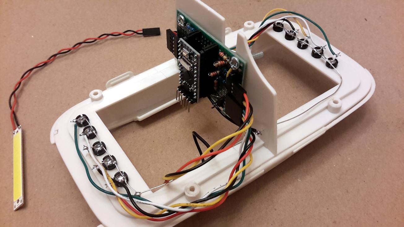
The connectors for the Arduino pro mini, the resistors, and the 2N2222 transistor are soldered to a 6cm x 4cm PCB (which is small enough to be mounted at the vertical wall in the middle of the headset.

Step 3: the LEDs and switches
The clear red 5mm LEDs are mounted with their clips and on each side their cathodes are soldered to a 5-pin cable. The anodes of all 10 LEDs are connected.


The three 3mm LEDs are hot-glued to the three bottom holes. Again, the catodes are soldered to a 3-pin cable, and their anodes are connected.

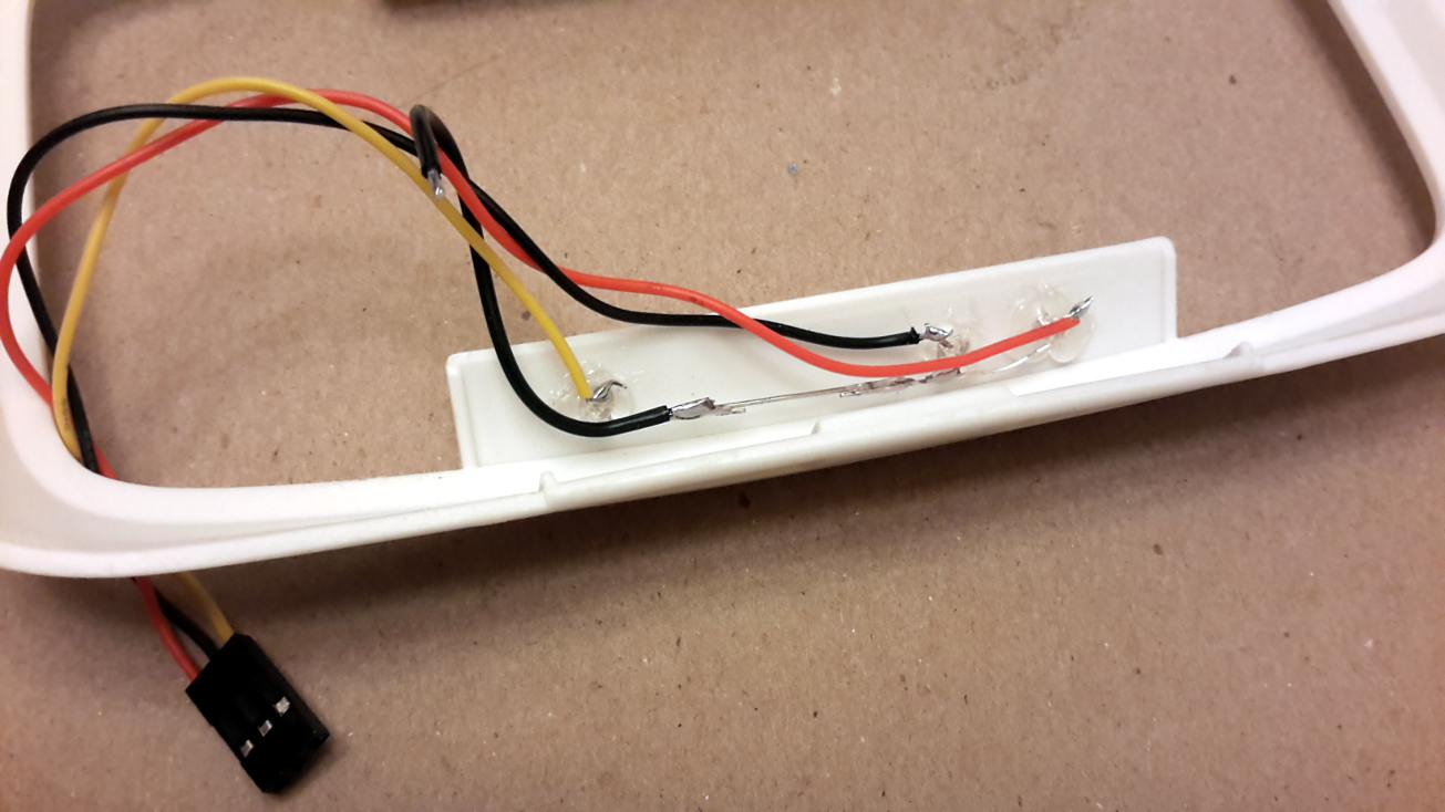
The three switches and the COD LED are also soldered to connector cables.

And everything is mounted to the headset.


Step 4: The Arduino Code and Operation
The Arduino code is basically the big brother of the "blink without delay" example sketch. The toggle switch at the front turns on the power. With the power is turned on, the two vertical rows with 5 red LEDs each are displaying different patterns. They may either only go up, or only down, or up and down in synch, or opposed to each other - or in a random walk. The three 3mm LEDs at the bottom blink randomly in 3-5 second intervals such that typically two (out of the three) LEDs are on.
The second toggle switch turns on a random flickering of the (very bright) cold white 1W COB LED at the top. In this mode, the momentary push button switch turns on a strobe effect of the COB LED.


That's it.
At night, these "Sci-Fi glasses" are a wonderful effect. They go nicely together with a "weird scientist" costume or, in my case, my Doc Brown outfit.