
The Chassis
When shopping at a thrift store, my son found this New Bright 1:15 R/C car for $3.50 which had approximately the right size for the droid.


We removed the body and found two motors. One is moving the rear wheels, and one is for the steering of the front wheels. Both were working.

The width (distance between the outer edges of the tires) is 8″, while the length (from front to rear wheels) is 10″. Based on the width we decided to build our mouse droid at 83% of the original size. This means that we had to increase the length of the chassis by 4.25″. Since the part with the rear wheels and the motor was just snapped onto the main part, it was easy to separate the two.


A 3-d Model
While deciding on the final measures of the mouse droid, I figured out my initial choice of a 83% scale would not work. I also thought that a 3D model could be helpful to check the proportions. I tried the free open source software OpenSCAD http://www.openscad.org and I immediately loved it. Based on the size of my RC car chassis, I came up with this 3D model (in the second image I removed the front and side plates). This corresponds to 90% of the original MSE-6 size.


At this point, I also decided not aim for a true replica. The original has only motors and sounds – and that would be too boring. Inspired by a YouTube video of a “Steam Punk” mouse droid with beautiful lights and display, I am also planning to add an ultrasonic sensor (for avoiding obstacles), some colored LEDs, an LCD display, and possibly something on the top that can be rotated by a servo. Here is the YouTube video: https://www.youtube.com/watch?v=yZ4ueUt2jhU
A LEGO Model
While I was busy with the CAD software, my son made another model, using LEGO.

Adjusting the Chassis
Earlier on, I had separated the rear axle from the front part of the RC car chassis since the width/length ratio of the RC car did not correspond to that of the mouse droid. Now I found, that the chassis has additional unused spaces where I could mount the rear axle at a larger distance from the front axle. This was very helpful, as I didn’t have to think about how to mount the rear and the front parts separately.


While the rest of the mouse droid is built from cardboard, there is one piece of wood for mounting the chassis.


While sitting in the kitchen and checking everything, I saw something move in front of the kitchen door. I could not believe my eyes, when it turned out to be a tiny furry fellow: A little mouse had joined me – possibly to check my progress on her favorite droid. It turned out that she was more surprised than me, and she gave me a chance to catch her with a glass bowl. As usual, I use such opportunities to take a few pictures.


Twelve Sheets of Cardboard
Yes, twelve sheets of cardboard – that’s basically all that was needed for our mouse droid. And some tools – in particular plenty of glue!

A great source of big sheets of sturdy cardboard is Sam’s Club. We grabbed a few of those big sheets that separate different layers of toilet paper or paper towels. From those we cut twelve pieces:
- Four pieces for the bottom (19 3/4in x 11in)
- Four pieces for the top (same size as bottom)
- Four pieces for the middle (18 1/4in x 10in)


the pieces for the top,


and the pieces for the middle part.

We started, gluing the four pieces for the middle layer.


Then we glued the two lower pieces for the bottom,


and we added the wooden plate to mount the chassis. We also cut the curved pieces for wheels,


add the two upper pieces for the bottom, stabilize the structure by adding some smaller pieces of cardboard, and check if the RC car chassis fits – it does!


Now, one can already recognize what this is going to be.

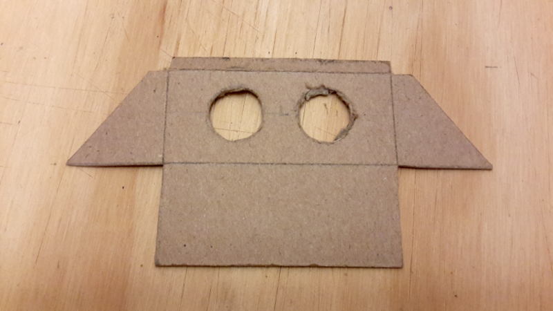
Cardboard for the Top
Very similar to the bottom structure, we proceeded with the top part. The only difference is that we left an opening in the right side, to access the electronics.

First we glued the outer borders of all four pieces, and then combined the inside regions.


Finally, everything was glued onto the bottom piece.

And this really looks like a mousedroid!


Adding Details and Smoothing the Edges
Now that the basic structure of the mouse droid was finished, it was time to add a few openings. Remember, we did not aim for a 1:1 replica of the original but wanted to add a few more details to make the appearance more interesting. These include:
- an ultrasonic sensor on the front side (for distance measurements – to avoid obstacles)
- an LED array on the front side (some blinking LEDs just look to good)
- a 4-digit, 7-segment display on the left side (this may e.g. display the current distance measurement of the ultrasonic sensor – and it will make the droid look more interesting)
- a few small LEDs, scattered over the circuit boards which will be mounted on the sides
We started with the cardboard structure to hold the ultrasonic sensor which will be mounted on the lower part of the upper front piece.
This was then mounted on the lower part of the front side.


One can also see the slit for the array of six LEDs. In addition, we cut a rectangle into the top right of the left side which will hold the 4-digit 7-segment LED display (no picture here, but this is visible in the last pictures of today’s post).
Now it was time to fill and smooth the edges where the corrugated cardboard structures are visible. We started by adding some white glue, to harden the cardboard, and we glued some thin cardboard around the middle plates.

Then we “painted” everything with a 1:1 mixture of glue and water to harden the surface.


Finally, we used wood filler to fill and smooth all edges.


On the next day, all edges were sanded and we obtained a beautifully smoothed body.


Painting the Body
It was time for some paint. My daughter found that beautiful “hammered black” from Krylon. Yes, the original MSE-6 is more a satin black, but we already mentioned that this was not going to be a 1:1 replica, right? My son suggested that this is the advanced model MSE-6c which includes improved electronics, as compared to the plain MSE-6. And with improved electronics, the droid also deserves improved paint!


And it looks really great. With all the excitement of adding the first layer of paint, we almost forgot to add structures to hold the access panel on the right side. So we made a few strips of multi-layered cardboard and glued those around the edges of the opening on the right side.


With these in place, we added a few more layers of paint. It turned out that it takes more layers of paint than we originally thought, and we had to get a second can of spray paint.

I really thought, that cardboard would not need a primer. But the next time I would probably start with a layer of cheaper paint before adding the slightly more expensive “hammered black”.

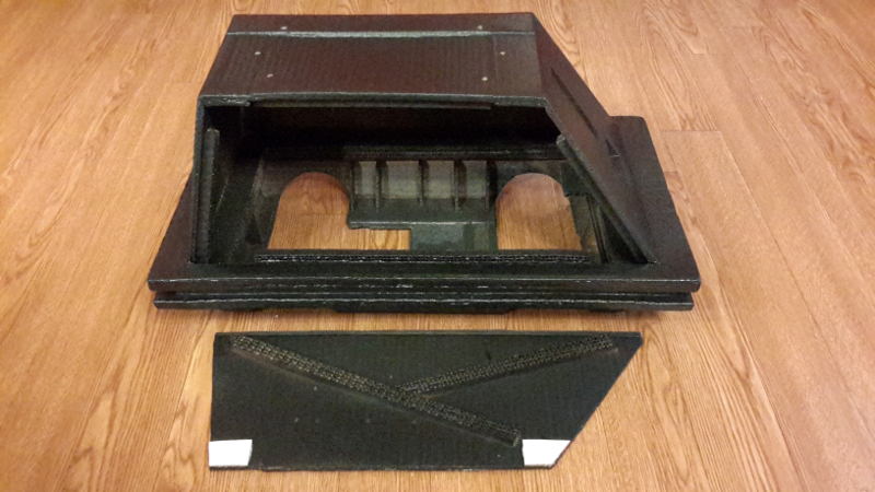
The Side Panel
Access to the inside of the mouse droid is gained through an opening on the right side. The panel that covers the opening is made from two layers of cardboard plus some cardboard structure for stability.


Freshly painted, this is how it looks from the outside.


Next, we looked for a mechanism to hold the side panel in place. We decided to use small magnets. Two magnets are sitting in two pieces of wood which are mounted in the top corners on the right side. We made some small holes in the wood pieces, inserted the magnets, and glued a layer of cardboard on top.


The other two magnets are held by two pieces of cardboard on the top of the side panel.


Now, the side panel is nicely held by the magnets, with a relatively weak force.

Details: PCBs and 7-segment LED display
We left a little rectangular opening on the top of the left side of the mouse droid. This is where we planned to place a 4-digit, 7-segment LED display, mounted in a thin piece of plywood. We prepared this plywood together with a plate that holds the on/off switch which is later mounted in the bottom of the back side.


The plywood pieces are then painted and the LED display and the on/off switch are mounted.


Then, we added the PCBs for the side panels. We mentioned before that we are not aiming for a 1:1 replica. So, instead of buying that huge number of 14 and 16 pin ICs, we simply recycled some PCBs that we had lying around. Some came from the RC car, and some from a broken CD-boombox. As spacers we used some corrugated straws.


These were painted matte black, and mounted on the left and right sides of the mouse droid.


The L-shaped PCB fits nicely around the LED display.

The Top Greeblies
One of the most recognizable pieces of the mouse droid are the top greeblies. Again, for this part we are not aiming for a perfect replica, but for something that resembles the style of the original. In addition to corrugated cardboard we are using different plastic straws and a cardboard tube (from a roll of parchment paper).


Some of the corrugated plastic straws were also used as separators for mounting the top greeblies. Everything is painted …


… and then mounted on the top of the mouse droid.


Once the RC car chassis is inserted …

… this is the side view on the mouse droid.

The LED Row
While the original mouse droid does not have any lights, we wanted to have a little “extra action”. So we created a vertical slot on the front side which holds six RGB LEDs (from which only the red and blue pieces are used). To improve the appearance, we placed the LEDs behind some matted, transparent plastic which we took from a gallon vinegar bottle.


The six RGB LEDs (common cathode) are connected to two 74HC595 shift registers (the six blue LEDs to the pins QB-QG of the first shift register, and the six red LEDs to the same pins of the second one).


Everything is then glued behind the slot on the front side …

… and this is the final front view.

Arduino, Electronics, Sound Module and Speakers
While we were building the mouse droid, I discovered the DFPlayer mini module which can play regular (44.1kHz, 16bit stereo) mp3 files. In another blog post I posted detailed instructions on how to connect this to the Arduino in way to avoid hum or buzz, with example code to demonstrate the basic functions, and links for further information. Here is the PCB that I made for the DFPlayer and a PAM8403, 2x3W stereo amp.

I got the sound files from the Yahoo Mouse Droid Builders group (under: Files -> Sounds -> Sounds for CFSoundIII), and normalized and converted them to mp3 format.
I still had two speakers lying around from a broken boom-box. One of them will be mounted on the side of the mouse droid, behind the PCB, and the other one to the cardboard chassis that is also holding the electronics and the battery pack. The second one will emit its sound to the ground which is not optimal, but I had no other place to hide the second speaker. Here is the cardboard chassis with a few frames to hold the Arduino, the motor controller, and the battery pack, with the speaker glued to it.

For the other speaker, I removed the larger PCB on the left side of the droid, cut a hole in the cardboard, and glued the speaker to the inside.


Usually speakers have a better bass-response when they sit in an enclosure, so I made two enclosures which will be glued over the backsides of the speakers.

T
The electronics is soldered onto an empty Arduino-shield PCB, including a HC-06 bluetooth module.

The MSE-6c droid is steered from an Android phone/tablet through a custom-made app, that I made using MIT App Inventor 2.

And here is the final result - Vader would be proud!
