Tuesday, December 10, 2019

Building Props for a Back-to-the-Future Time Machine - Part 4: The Analog Gauges


My other blog posts on BTTF props:
  Part 1: Building a Flux Capacitor
  Part 2: Building the Time Circuits
  Part 3: Building the Speedometer
  Part 5: Building the TFC Switch

After building the Flux Capacitor, the Time Circuits, and the speedometer, the next logical thing were the Analog Gauges. That triangular device that fits the glove compartment on the passenger side with those three beautiful old analog gauges and the red light which signals when you are running out of plutonium.

Some Time Machine builders are really trying to get the original old analog gauges like those used in the movie prop. But this would be too expensive, and not an option for me. I decided to buy three inexpensive Voltmeters and an illuminated red push button switch, and do the rest with 3/16" plywood and a laser cutter.


I disassembled the voltmeters and the push button switch. For the push button switch, I printed he word "EMPTY" (in Eurostile Bold font).


I designed the labels for the gauges in the open-source software scribus, for printing as 4" x 6" glossy photos. Here are the source images...


... and these are the printed photos.


The voltmeters are glued to the wood, and the labels are inserted.


The combined unit is then glued to the front plate.


Small holes are drilled for mounting the LEDs (5mm straw hat LEDs, which have a wider light cone).


The LED wires are bent so that the LEDs are facing upwards.


And the LEDs are glued onto the panels.


The electronics, based on a Arduino pro mini (ATmega 168, 16MHz, 5V), is assembled on a small PCB.


Everything is painted and the acrylic front pieces are inserted and held by additional wooden pieces.


Since my version is not mounted in the DeLorean's glove compartment, I need a full enclosure. 


And that's it. Here is the final unit.


And here, again, when the front panel LEDs are illuminating the gauges.


This unit does not have a sound player. But this piece is connected to the Time Circuits module and the two are communication via a serial connection. After turning on the Time Circuits, after three seconds, it send a signal to the Analog Gauges which then turn on. At that point the Time Circuit module is playing the "turn-analog-gauges-on" sound. 

Related:

My other blog posts on BTTF-related props and pieces:
   - Building the Time Circuits
   - Building a Hoverboard and Charger
   - Building BTTF clocks
   - Building a BTTF Brick Stage (featuring the smallest Flux Capacitor)


Friday, November 15, 2019

Building Props for a Back-to-the-Future Time Machine - Part 3: The Speedometer


My other blog posts on BTTF props:
    Part 1: Building a Flux Capacitor
    Part 2: Building the Time Circuits
    Part 4: Building the Analog Gauges
    Part 5: Building the TFC Switch

After I built the Flux Capacitor and the Time Circuits from the DeLorean in "Back to the Future", I just couldn't stop. The next piece was the speedometer that is sitting on the dashboard of the DeLorean, which prominently displays the "88" mph to indicate the time-jump.

My initial plans were to make a simple non-functioning prop, that maybe counts from zero to 88, and after a short break, makes a countdown. Later, however, I could not resist to add a GPS receiver, so the final version is a fully functioning GPS speedometer.

Enclosure

As in my other BTTF-related builts, the case is made of 3/16" plywood with a laser cutter.


The pieces are glued and painted (with Rustoleum, gloss, almond) , and it instantly resembles the original prop.

Electronics

The electronics of the speedometer is built around an Arduino pro mini (168, 16MHz, 5V), two red 0.8" 7-segment LED displays (common anode), two shift registers TPIC6B595 (which can sink 100mA per pin, so no further transistors are needed), a Neo-6M GPS module, plus sixteen 220 Ohm resistors (8 for each display: 7 segments + decimal point).


The images do not show the Neo-6M GPS module which was an afterthought. Later, it was placed in the space on the left on the picture above. While I found many postings on the web of people having trouble, the Neo-6M module works really well for me (although I connected it via soft-serial, which people do not recommend - but I never had problems).

Of course, one needs to add the labels from the DYMO 1540 Office Mate II label maker (which I bought for the Flux Capacitor labels) - these are an essential piece for recognizing this prop. And here it is ...


... and here, working in my car.


But the usage is not restricted to the car - it also works well on my bicycle (with the battery pack placed in the cup holder).


Related

My other blog posts on BTTF-related props and pieces:
   - Building a Flux Capacitor
   - Building the Time Circuits
   - Building the Analog Gauges
   - Building the TFC Switch
   - Building a Hoverboard and Charger
   - Building BTTF clocks
   - Building a BTTF Brick Stage (featuring the smallest Flux Capacitor)

Tuesday, November 5, 2019

Building Props for a Back-to-the-Future Time Machine - Part 2: Time Circuits


My other blog posts on BTTF props:
    Part 1: Building a Flux Capacitor
    Part 3: Building a Speedometer
    Part 4: Building the Analog Gauges
    Part 5: Building the TFC Switch

My Back-to-the-Future obsession started while I built the Flux Capacitor. After finishing this, I knew that I also wanted to build some of the other props that are featured in the DeLorean time machine. The second most interesting prop were the Time Circuits. After a little research, I was somehow hesitant to start this, as the electronics side would become rather complex, plus some of the pieces would be hard to find. The reason for this are the alphanumeric (16-segment) LED displays on the left that display the months. Many helpful details and complexities on this issue have been investigated and documented by a fellow builder.

Then I saw the blog at the Adafruit page, where they simply use 7-segment displays for all the fields. Furthermore, the electronics setup is really easy, as they are using nine combined 4-digit 7-segment displays. Initially, I found that the Adafruit built looks a little lame, but then I concluded that much of this is due to their oversimplified enclosure. I thought that by applying my recent laser-cutter skills, I would be able to build Time Circuits, much closer to the real thing.

Electronics

I started with the electronics: From Aliexpress, I got a DS3231 RTC clock module, nine 0.56" 4-digit 7-segment LED displays, a DFPlayer Mini (plus 128MB micro SD card), and an Arduino Mega. The nine LED displays are slightly different from those used in the Adafruit blog, which are I2C based. My displays are based on the TM1637 chip, so there are no problems due to limited I2C addresses. 

There are many references on the web for a bug in the DS3231 RTC clock module (it is usually operated with non-rechargeable battery, which can be damaged by the charging circuit on the module). I used the solution described on this page and unsoldered resistor R5 on the board. It's been running fine since more than a year now with the original battery.

For the keypad, I used a cheap 12 button keypad (yes, the original prop has only 10 buttons). This is connected to an Arduino Mega analog input with a single wire, using the solution described in my previous blog.

Enclosure

Just like my Flux Capacitor, the enclosures for the Time Circuits and my other Time Machine props are built from 3/16" plywood cut with a laser cutter. The enclosure for the Time Circuits is roughly based on the size of the original prop, but slightly adjusted to fit my LED modules.

In contrast to the "flat" Adafruit version, the three rows are stacked as in the original. In between the rows, I left a tiny space (1/16") which adds a lot to the appearance.


The labels were made in scribus (open source desktop publishing software) using the Microgramma Bold Extended font, and printed on glossy 4"x6" photo paper.

Car Holder

At this point I have to admit that I do not own a DeLorean. My Time Machine props will have to operate in a Toyota Camry (I know: no style at all). After many iterations, starting with cardboard templates and various plywood versions, I came up with this shape.


This nicely fits the space above the radio and holds well due to friction.

Functions

The middle row always displays the current date and time. The top and bottom rows display dates and times that appear in the movies, or birthdates of the actors. After a random time interval (small number of minutes) to top row is copied into the bottom row, and a new random date is diplayed in the top row. The user can enter data via the keypad (which produces the DTMF tones), and there are different options:

  • Entering a single digit number plays a song from the movie ("Power of Love", "Back in Time", "Earth Angel", "Johnny B Goode", the ZZ Top song, or some orchestral pieces)
  • Double digit numbers are not yet used - in a future update, I plan to use these to play some of my and my family's favourite songs.
  • Four-digit numbers are interpreted as years. When a four-digit number is entered, and new date/time entry appears in the top row, where the month/day and time is taken from the previous entry. And the previous entry is copied into the bottom row.
  • Eight digit numbers are interpreted as month/day/year. The rest is like in the previous case.
  • Twelve-digit numbers are interpreted as month/day/year/hour/minute and displayed in the top row.
If an entry is not valid (invalid number of keys, or invalid values), a buzzing sound is played.

A wonderful detail is that my code for reading the clock includes a correction for Daylight Savings Time. This makes it the only clock in our household that I don't have to adjust by hand, twice a year.

Related

My other blog posts on BTTF-related props and pieces:
   - Building a Flux Capacitor
   - Building a Speedometer
   - Building the Analog Gauges
   - Building the TFC Switch
   - Building a Hoverboard and Charger
   - Building BTTF clocks
   - Building a BTTF Brick Stage (featuring the smallest Flux Capacitor)

Tuesday, October 1, 2019

Building the Doomsday Machine from "The Pink Panther Strikes Again" - Part III: Electronics, Arduino, Raspberry Pi

Now it's less than two weeks that our local Community Theater will be performing "The Pink Panther Strikes Again", in which Dreyfus threatens to destroy the world with a Doomsday Machine - which I volunteered to build. My version is made of three parts: A base, a center piece (holding a computer screen, joystick, buttons, and lights), and a "laser gun" at the top. In Parts I and II of this post, I finished the enclosures. Now I address the electronics, and the programming of the Arduino and Raspberry Pi computers.

My other blog posts for this build:
    Doomsday Machine Part I: Wooden Structures
    Doomsday Machine Part II: Finishing the Enclosure

Lights for the Laser Gun

[Mon, Sept. 30]  To achieve a great effect in the play, the Laser Gun has to be very bright. For this purpose, I am using  a 2835 LED Strip. I am using the cold white version (which is brighter than warm white) and the non-waterproof type (easier to solder).


This strip has 120 LEDs per meter, or 60 LEDs per 20" (=50cm), which is the length of the pieces that I will glue to the barrel of the laser gun (six pieces) and to the front rod (one piece).


The wires go through a small hole in the barrel of the gun.

I am really happy that the glue of the LED strip holds really well to the painted cardboard.

The LED strip, glued to the rod at the front is supported by a few cable ties. 

Since I did not have much experience with LED strips, so far, I was a little worried that they might not be bright enough. But, as it turns out, I don't need to worry about this. They are extremely bright.

Lights in the Center Piece

[Tue, Oct 1]  The center piece has ten openings for LEDs. I am using 8mm, 0.5W Straw hat LEDs. The LEDs are glued to two pieces of plywood.


20 Ohm, 1W resistors are directly soldered to the Anodes and connected to each other.

Circuit Board 

[Thu, Oct 3] Now, it's time to approach the circuit board. The circuit is based on an Arduino Pro Mini (ATmega 168, 16kHz, 5V), two shift registers 74HC595, ten transistors 2N2222 (for the 0.5W 8mm LEDs) 7 MOSFET transistors IRLB8721 (for the LED strips), and it is powered by a 12V/48W power supply (those that you buy for LED strips) and a voltage regulator LM7805 (reducing the 12V to 5V for the Arduino and the 8mm LEDs. (I may post more details on the circuit later - either here, or in a separate blog post). 
This is the least rewarding piece of the work. For the enclosure, you can see your progress in every step - the same applies to the programming. But for the assembly of the circuit board, you can only hope that you did not forget any connections, potentially resulting in an extended bug-search. In any case, you should start with a detailed plan for the layout of the circuit on your PCB. 


Then, after 3-4 hours of soldering, it looks like this.


A first quick test of the power and ground lines shows that I forgot a connection of the +5V line to one of the shift registers. This is quickly fixed (and I really hope this was the only bug).  After uploading a little test program to the Arduino, I'm connecting the 12V power supply to test if I can address all the LEDs and LED strips.

[Sat, Oct 5] I connected all the pieces. I soldered wires to the LED Cathodes and to the common Anode,

screwed the LED holder panels into the Center Piece, and connected all the cables to the circuit board (from the LEDs, the push buttons and the joystick). As a little extra-feature and Easter Egg, I also added a piece, that I built earlier as part of my set of Back-to-the-Future props: the Analog Gauges that sit in the glove compartment of the DeLorean.

At this point, I took everything to the theater. Here, I screwed the Laser gun on top of the center piece and connected the cables from the LED strips to the circuit board. 

In the Arduino code, I am using the ShiftPWM library to control the brightness of the individual LEDs and LED strips through the shift registers. I am using this in "high resolution" mode (with 255 levels of brightness) and it works very well. The LED strips have a range from dim to unbelievably bright.

When everything is mounted on top of the base and moved to the stage, it's a really impressive view (but the very bright lights make this very hard to capture).

[Tue, Oct 8] It still took me a while to finish the coding. The Raspberry Pi is set up such that it starts automatically, plays a short start-up video on the screen (featuring a Pink Panther), and then continues to loop another video showing animation of a "SciFi" computer screen (all in green, like those 1970's-80's computer screens). 
The Arduino is reading the push buttons and the joystick and controlling the LEDs, and has five modes of operation: (1) when powered on, there is some low-level activity of all LEDs. (2) a little more activity, when Dr. Fassbender fiddles with the controls, (3) the LED strips are moving slowly from the back to the front, when Dr., Fassbender starts the countdown to destroy the UN building, (4) the same pattern, but faster when Dreyfuss accelerates the countdown, and (5) increasing erratic activity when Dr. Fassbender starts the self-destruct mode.
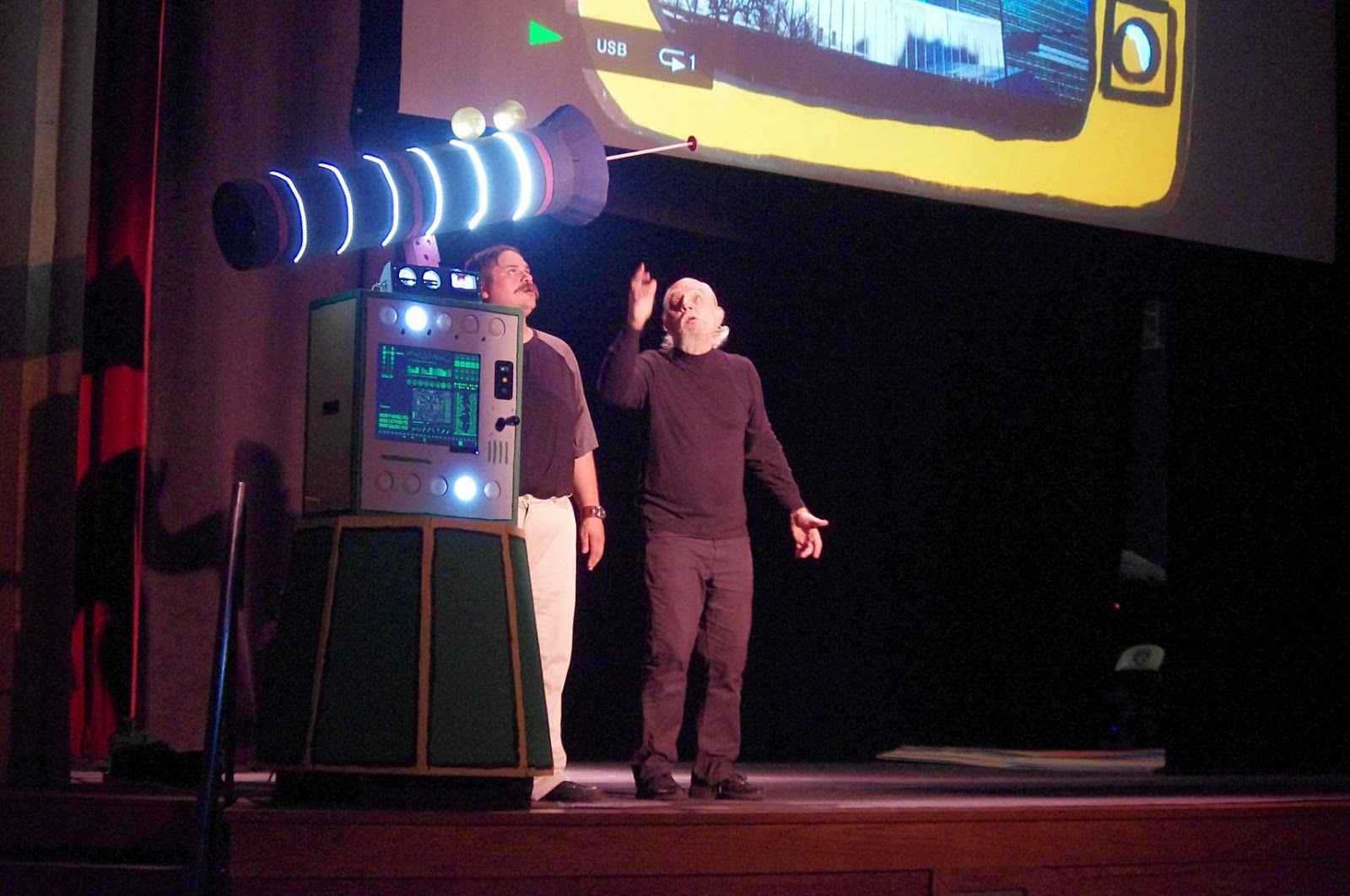
Here is the final Doomsday Machine on stage.


The following pictures show a quick run-through (the actors not yet wearing costumes), how they start the countdown,


the machine fires,

and the laser reaches the UN building.


Other posts on the Doomsday Machine: