Showing posts with label laser cutter. Show all posts

Tuesday, December 29, 2020

Building "Totoro" and "2001: A Space Odyssey" Themed Tissue Box Covers


While thinking of ideas for Christmas presents, I saw those ugly tissue boxes on our kitchen counter. That reminded me of a plan I had long ago, to cover those in some pretty wooden cases.
With the laser cutter at hand, I liked the idea of having some of our family favorites on there - which brought me to "Totoro". And while I was getting started, also the "2001: A Space Odyssey" movie cme to mind. So I built two of each.

Size and Design

I checked some of the tissue boxes that we had around from Kleenex, Puffs, and Great Value. They are all slightly different, but they all fit inside the following size: 4 3/4" x 4 7/8" x 5 1/4" (high). Their oval openings also differ, but all could be used with an opening of 3 3/4" (long diameter) and 2 5/8" (short diameter). I used two different approaches for the "Totoro" and the "2001" boxes: For the Tototro box, the figures a glued onto the box surface, so they stick out, while for the 2001 box, the figures are made as inlays.

CAD Files for the Laser Cutter

Step one is getting the laser cutter files done, using librecad. First comes the shape for the box.


And here are the two cutouts for the Totoros.


The "2001: A Space Odyssey" designs are cut into the sides of the box. These are an ape with a bone, Dave Bowman walking in his red space suit through the corridor while carrying the AE-35 unit, HAL 9000, and the Discovery One spaceship.  


Assembling the Pieces


Once everything is cut, the sides are cleaned from the burnt dust, ...


... glued, and held by rubber bands while the glue is drying.


The next step (not shown here) is to round the corners. I started with a disk sander and finished doing the details by hand. 

The painting is then the fun part. First some beige for the box, then grey, white, green, black, and purple for the Totoros and their tiny details. 


And here is the final Totoro Box cover.


And here are the same steps for the "2001" box.


The only difference between the two boxes is that the 2001 figures are made as inlays. This requires gluing some thin cardboard behind the box openings.


And here are the two 2001 box covers with their four different sides.


Saturday, June 27, 2020

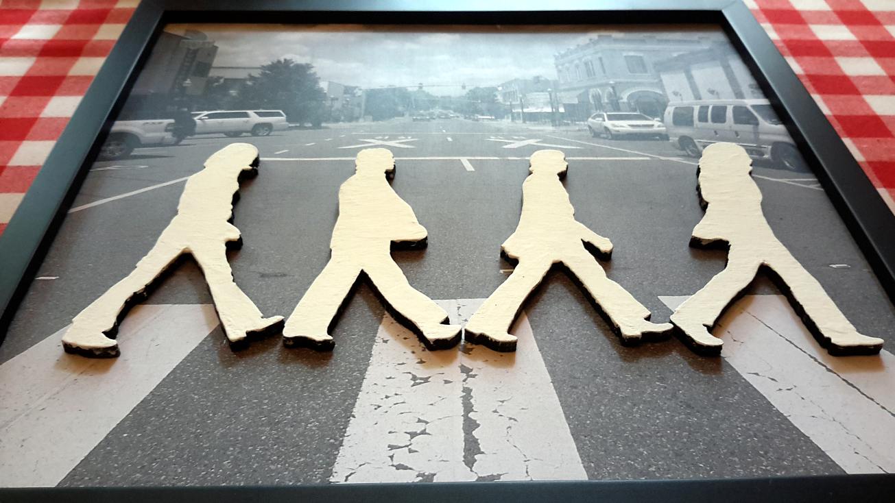
The Beatles - Trenton Rd


A little project, in between...

Starting with a photo of Trenton Rd, in Ruston LA...


...and a little editing.


Tracing the Fab Four (in librecad) and cutting them with a laser cutter. 


Some white acrylic paint.


Gluing the printed image onto plywood, and placing it in a frame. Then, checking the LP cover for the precise positioning, ...


... and finding a nice spot in the kitchen. 


Monday, January 13, 2020

Building Props for a Back-to-the-Future Time Machine - Part 6: The SID panel


My other blog posts on BTTF props:
  Part 1: Building a Flux Capacitor
  Part 2: Building the Time Circuits
  Part 3: Building the Speedometer
  Part 4: Building the Analog Gauges
  Part 5: Building the TFC switch

This is now the last of the Time Machine props that I am building: The "SID panel" (Status Indicator Display) which sits in the DeLorean behind the drivers seat (right from the Flux Capacitor). It does not have any obvious function, but it looks cool in the movie when Marty approaches 88mph and you can see behind him, more and more of the 200 LEDs in this panel starting to light up: One row (= ten) red LEDs, siz rows of yellow LEDs, and thirteen rows of green LEDs. The good thing is that these days LEDs are dirt cheap (like 100 for $0.99 at Aliexpress). The bad thing is that in the original prop, each LED is mounted inside a little plastic holder - and these holders cost like $0.50 a piece (and 0.5 * 200 = ... too much). But I never went for 100% accuracy, so I just omit these holders. With this, I think the whole SID cost me less than $15.

The construction of the enclosure is straightforward.


It was fun, to watch the laser cutter cutting the 200 holes, and the result is, of course, very precise.


Now that the enclosure is glued and painted, it's time to address the electronics. Unlike for the other BTTF Time Machine props, the matrix circuit (and, later, the Arduino programming) for the 200 LEDs is a little more complex. 


The LEDs are soldered onto three 9cm x 15cm PCBs, as a matrix.


The electronics is based on an Arduino Pro Mini (ATmega 328). The LED matrix is accessed by a decimal counter (CD4017) for the 10 columns (together with two MIC2981 drivers), and three chained shift registers (TPIC6B595, which can sink larger currents than the 74HC595) for the 20 rows.


The code require a few more thoughts: My SID panel will operate in two modes: 1) standalone and 2) connected (via serial) to the other Time Machine props, so it gets the information of the current speed from the speedometer - and it can adjust the LED activity to the speed.
In both modes, the LEDs are moving randomly up and down. In mode 2) the random activity is coupled to the speed, while in mode 1) a speed value of 40 is assumed. The up and down motion of the individual LEDs columns is, however, not independent. If, for a given column, the two neighbors are higher, this increases the probability for this column to rise. Also, if a column was rising before, the probability is higher for this column to continue to rise in the next step. When a column has reached its max or min value, it will sit there for a while (the time is, again, random) and then change it direction. All the probabilities mentioned here are speed-dependent, such that the overall activity also changes with the speed. At zero speed, the columns are typically only moving up to the 5th row, while at 88 on average more than half of the columns will go all the way up, into the red.


After spending too much time on BTTF forums, I concluded that I had to add some corrugated plastic pipe (of about 3/4" diameter) which is held by two P-clamps (I could not find any purple ones, like in the movie prop, so I had to settle for black), through which the power/serial cable coming from the TFC switch is led. 


Here, the final unit is operating on the back seat of my car (no, it's not a DeLorean...).


Related:

My other blog posts on BTTF-related props and pieces:
   - Building BTTF clocks
   - Building a BTTF Brick Stage (featuring the smallest Flux Capacitor)


Tuesday, January 7, 2020

Building Props for a Back-to-the-Future Time Machine - Part 5: The TFC Switch


My other blog posts on BTTF props:
  Part 1: Building a Flux Capacitor
  Part 2: Building the Time Circuits
  Part 3: Building the Speedometer
  Part 4: Building the Analog Gauges

Introduction

The TFC switch is the center piece of the time machine. It is certainly not as attractive as the Flux Capacitor, the Time Circuits, and not even as the Speedometer or the Analog Gauges. But it is the unit that turns all the others on and off.

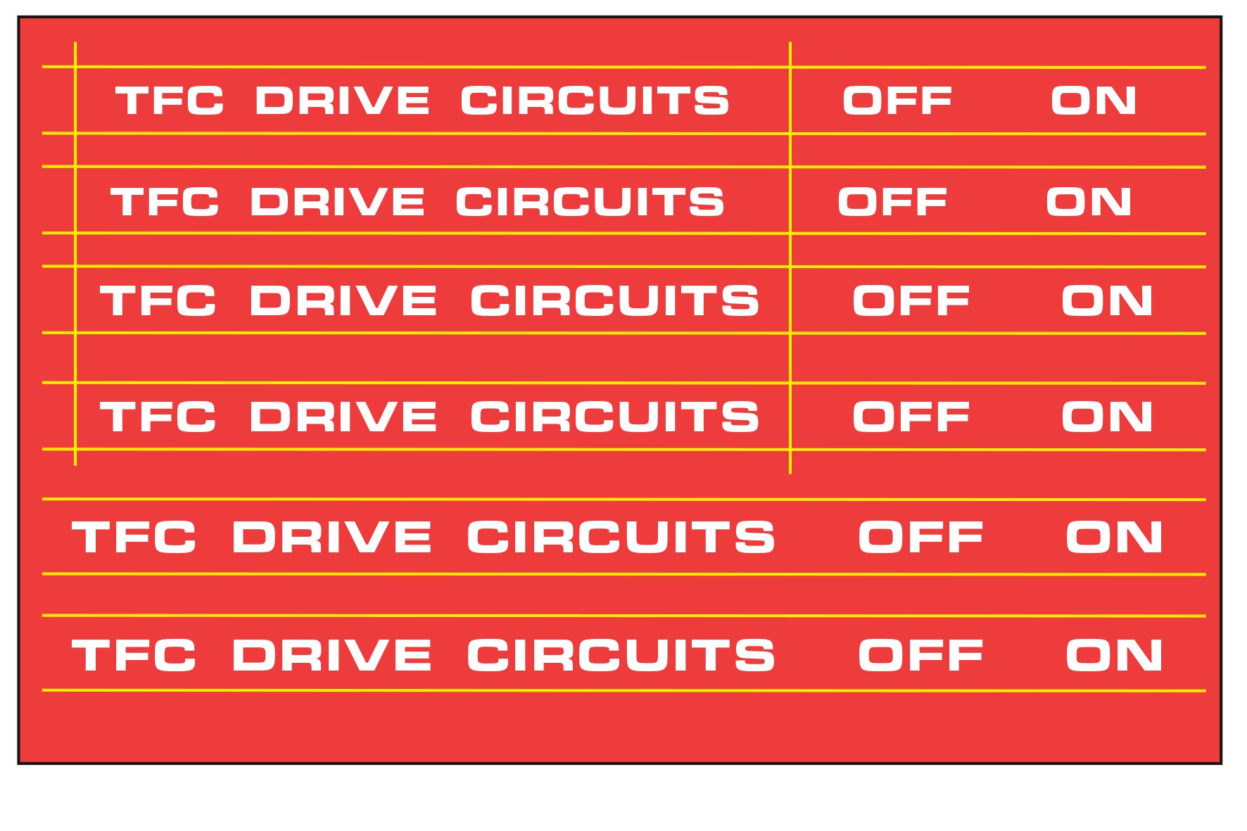
The most recognizable elements are the handle (built from a battery terminal cleaner like the Lynx 3-in-1 battery brush, https://www.pepboys.com/lynx-battery-brush/product/9405475) which is mounted on a Dayton Drum Switch (https://www.grainger.com/product/DAYTON-Maintained-Reversing-Plastic-2X442, with the top cover replaced by transparent acrylics). Other than that, it consists of eight switches, one potentiometer, and two lamps, all in a Radio Shack project box (8 x 6 x 3 inches, Model Number 270-274). The labels are matching the other labels on the time machine pieces, either from a 1980's style label maker, or with a white Eurostile Bold Extended (or Microgramma Bold Extended) font on a red background.

Using the above links, one could simply buy all the pieces and get a very precise reproduction of the original prop. However, the drum switch alone costs more than $100. Like my other props, I want to build this thing from scratch, mostly using wood (plywood) and a laser cutter.

Building

I am starting by cutting all pieces from 3/16" plywood with a laser cutter.


Here are the pieces for the bottom box, together with the switches and lamps. I got all the switches and lamps from Aliexpress. While the lamps in the original prop have beautiful jewel lenses (which you can still get ... but not cheap), I used two LED lamps of similar size with simple, but good-looking plastic covers.


The box is glued and painted.


Here are the pieces for the Drum Switch.


First, the holders for the rod are painted black.


The side pieces are glued onto the base plate.


Some wires and PCB pieces are used to make the inside of the switch look interesting. 


Now, the challenge is to bend the acrylics plate to shape.


The first half went really well...


... but the second half became really ugly. The acrylics bent weirdly, and at one screw hole it broke. This will be redone later.


Some labels are made using a Dymo label maker, and the others are printed on 4"x6" photo paper. Those for the enclosure...


... and those for the Drum Switch.


Then they are glued onto the box.


This looks really nice already (remember: the warped acrylics will be replaced!).


I am planning to use the Drum Switch to actually turn on/off the while time circuits, so I need to add some functional switches. For this purpose I am adding two micro switches which are closed by a lever in the Drum Switch.


In this configuration, my Drum Switch is not an on/off switch. It is only pressing two momentary push buttons (the micro switches). The on/off effect is later done in software.


I did say that I am building everything from scratch: Here is the handle for the switch. (The ends of the switch are not angled like the ones on the original battery terminal cleaner. I did not know how to achieve this with my wood-tools.)


 And the lever can be seen here in contact with one of the micro switches.


The Drum Switch gets the original "Dayton" sticker.


Inside the TFC switch is an Arduino Pro Mini which is reading the switches and operating the lamps. Via serial connection this Arduino is communicating with the Arduinos in the other components of the Time Machine. 


After another acrylics plate was bent for the Drum Switch (this time successfully!), the TFC Switch is complete. This is how it looks from all sides.


Related:

My other blog posts on BTTF-related props and pieces:
   - Building the Time Circuits
   - Building a Hoverboard and Charger
   - Building BTTF clocks
   - Building a BTTF Brick Stage (featuring the smallest Flux Capacitor)