My other blog posts on BTTF props:
Part 1: Building a Flux Capacitor
Part 3: Building a Speedometer
Part 4: Building the Analog Gauges
Part 5: Building the TFC Switch
My Back-to-the-Future obsession started while I built the Flux Capacitor. After finishing this, I knew that I also wanted to build some of the other props that are featured in the DeLorean time machine. The second most interesting prop were the Time Circuits. After a little research, I was somehow hesitant to start this, as the electronics side would become rather complex, plus some of the pieces would be hard to find. The reason for this are the alphanumeric (16-segment) LED displays on the left that display the months. Many helpful details and complexities on this issue have been investigated and documented by a fellow builder.
Then I saw the blog at the Adafruit page, where they simply use 7-segment displays for all the fields. Furthermore, the electronics setup is really easy, as they are using nine combined 4-digit 7-segment displays. Initially, I found that the Adafruit built looks a little lame, but then I concluded that much of this is due to their oversimplified enclosure. I thought that by applying my recent laser-cutter skills, I would be able to build Time Circuits, much closer to the real thing.
Electronics
I started with the electronics: From Aliexpress, I got a DS3231 RTC clock module, nine 0.56" 4-digit 7-segment LED displays, a DFPlayer Mini (plus 128MB micro SD card), and an Arduino Mega. The nine LED displays are slightly different from those used in the Adafruit blog, which are I2C based. My displays are based on the TM1637 chip, so there are no problems due to limited I2C addresses.
There are many references on the web for a bug in the DS3231 RTC clock module (it is usually operated with non-rechargeable battery, which can be damaged by the charging circuit on the module). I used the solution described on this page and unsoldered resistor R5 on the board. It's been running fine since more than a year now with the original battery.
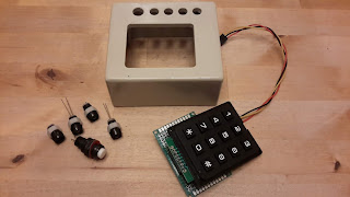
For the keypad, I used a cheap 12 button keypad (yes, the original prop has only 10 buttons). This is connected to an Arduino Mega analog input with a single wire, using the solution described in my previous blog.
Enclosure
Just like my Flux Capacitor, the enclosures for the Time Circuits and my other Time Machine props are built from 3/16" plywood cut with a laser cutter. The enclosure for the Time Circuits is roughly based on the size of the original prop, but slightly adjusted to fit my LED modules.
In contrast to the "flat" Adafruit version, the three rows are stacked as in the original. In between the rows, I left a tiny space (1/16") which adds a lot to the appearance.
The labels were made in scribus (open source desktop publishing software) using the Microgramma Bold Extended font, and printed on glossy 4"x6" photo paper.
Car Holder
At this point I have to admit that I do not own a DeLorean. My Time Machine props will have to operate in a Toyota Camry (I know: no style at all). After many iterations, starting with cardboard templates and various plywood versions, I came up with this shape.
This nicely fits the space above the radio and holds well due to friction.
This nicely fits the space above the radio and holds well due to friction.
Functions
The middle row always displays the current date and time. The top and bottom rows display dates and times that appear in the movies, or birthdates of the actors. After a random time interval (small number of minutes) to top row is copied into the bottom row, and a new random date is diplayed in the top row. The user can enter data via the keypad (which produces the DTMF tones), and there are different options:
- Entering a single digit number plays a song from the movie ("Power of Love", "Back in Time", "Earth Angel", "Johnny B Goode", the ZZ Top song, or some orchestral pieces)
- Double digit numbers are not yet used - in a future update, I plan to use these to play some of my and my family's favourite songs.
- Four-digit numbers are interpreted as years. When a four-digit number is entered, and new date/time entry appears in the top row, where the month/day and time is taken from the previous entry. And the previous entry is copied into the bottom row.
- Eight digit numbers are interpreted as month/day/year. The rest is like in the previous case.
- Twelve-digit numbers are interpreted as month/day/year/hour/minute and displayed in the top row.
If an entry is not valid (invalid number of keys, or invalid values), a buzzing sound is played.
A wonderful detail is that my code for reading the clock includes a correction for Daylight Savings Time. This makes it the only clock in our household that I don't have to adjust by hand, twice a year.
- Building a Flux Capacitor
- Building a Speedometer
- Building the Analog Gauges
- Building the TFC Switch
- Building a Hoverboard and Charger
- Building BTTF clocks
- Building a BTTF Brick Stage (featuring the smallest Flux Capacitor)
Related
My other blog posts on BTTF-related props and pieces:- Building a Flux Capacitor
- Building a Speedometer
- Building the Analog Gauges
- Building the TFC Switch
- Building a Hoverboard and Charger
- Building BTTF clocks
- Building a BTTF Brick Stage (featuring the smallest Flux Capacitor)


2 comments:
Wow, Laser Cutter, you are already in the futur for me. Very nice project.
Richard, I understand exactly where you are coming from. I do not own a laser cutter, but I am very lucky to have access to one. Two years ago, that would, indeed, have felt like the future.
Post a Comment