Part I of the movie also features another important clock which is part of the "Twin Pines Mall" sign (which, after Marty changed the timeline, became the "Lone Pine Mall").
I had this idea quite some time ago, and the electronic parts all at hand, when a posting of another build in the "Back to the Future Forever" facebook group inspired me to get this started.
Electronics (I)
The electronics is built around an Arduino Nano.
The time is displayed on a 8x32 LED array, based on the MAX7219 driver IC - this looks rather close to the display in the original movie prop. The differences are that in the original movie prop the colon is not exactly aligned with the grid of the dot matrix, and the "AM"/"PM" displays use a smaller dot matrix). But for my purposes this is close enough.
For the real time clock (RTC), I am using the module DS3231 which I also used previously in the Time Circuits. This clock is very precise and it runs for years with a CR2032 battery. There is, however, one problem with this modul, related to the charging circuit which is supposed to be able to charge a rechargeable battery. As discussed in detail on this web page, the charging circuit would do damage to both a rechargeable battery or a non-rechargeable battery. So, the suggested solution is to simply remove a resistor (as indicated in the image) and to operate the module with a (non-rechargeable) CR2032 battery - and that's what will I do.
I also add a light dependent resistor (LDR) to the circuit, so the clock can adjust the LED intensity based on the surrounding brightness.
My test-setup (using an Arduino Uno) works fine.
Enclosure
The LED matrix defines the size of the unit - the enclosure is scaled accordingly to 5 1/8" x 21". The outer part of the enclosure is built like a picture frame using 3/4" thick and 3 1/2" wide pine boards, cut with a miter saw, glued, and sanded.
The additional pieces are cut with a laser cutter from 3/16" plywood and clear acrylics.
For the first time, I used the program inkscape, so I could cut the letters for "Twin Pines Mall".
Everything is painted using acrylic paints.
The pair of trees are made from two layers of 3/16" plywood plus two additional triangular pieces cut with a table saw.
This is the enclosure.
Electronics (II)
The electronics is soldered on a 6cm x 8cm PCB. First comes a sketch...
... and then the soldering.
Everything is connected...
... and inserted into the enclosure.
The Final Unit
Here it is: my "Twin Pines Mall" clock (with two Lego figures as a reference).
In this fifth part of my GERTY 3000 build blog, I will finish my replica. First, I describe all of GERTY's functions and then how this is achieved in hardware and software.
But first, have a look at the final GERTY 3000 in action (with a cameo appearance of my HAL 9000 unit)
GERTY 3000's Functions
Gerticons & Sound Clips
At startup, Gerty shows a series of images simulating the boot procedure (over 30 seconds). After that, the two lamps and Gerty's blue eye fade on, and Gerty "default" face with the smile appears on the screen.
The main obvious function for Gerty is to display the faces on the LCD screen. This is accompanied by variations of the blue eye and the two lamps. When the PIR sensor detects motion, random Gerty sound clips from the movie are played. To ensure that this doesn't get annoying, these sounds are played not more than once every 4-8 minutes (the time-interval is varied randomly). Random sounds are also played after 20 minutes of silence.
Responding to Voice Input
A two-level hotword recognition software (running locally, i.e. without internet access) first recognizes the word "Gerty", based on which Gerty replies with "Yes, Sam". This starts the second level in which the software is waiting six seconds for any of the following 13 phrases:
Tea timer [starting the tea timer]
Turn on the Light [increasing the brightness of the two lamps]
Weather forecast [displays the weather forecast for the next 3 days]
What's the news? [displays current news headlines]
Appointments [displays all events from the Google calendar for the next 48 hours]
Am I a clone? [replies with the corresponding response from the movie]
Where am I? [replies with the corresponding response from the movie]
You need to let me go outside [replies with the corresponding response from the movie]
What are you talking about [replies with the corresponding response from the movie]
You will be o.k.? [replies with the corresponding response from the movie]
The bottom six phrases are statements made by Sam Bell in the movie, and GERTY will respond accordingly. (e.g.: "Where am I?" - "Sam, you're in the infirmary, you had an accident. Do you remember what happened?" or: "Am I a clone?" - "Sam, there was no crash. You were being awakened." or: "You will be o.k.?" - "Of course, the new Sam and I will be back to our programming as soon as I finish rebooting.")
Fetching Data from the Web
Three of the above voice commands result in fetching data from the web (Google calendar, news, weather). In addition, Gerty is checking the Google calendar every 15 minutes for events scheduled withing the next 20 minutes.
Two Push Buttons
Gerty has two push buttons on the side, one to start the tea timer (I planned this before implementing the voice recognition) and one to shutdown (short press) or reboot (long press) Gerty.
Electronic Circuits
In the previous part, I already showed photos of the PCBs with the electronics. Here, I also document the rather minimal electronics circuits. The first one is for the Arduino Nano.
The Arduino Nano is connected to a Raspberry Pi 3B+ via a USB cable. This serves as the serial data connection between the two and also to power the Arduino from the Raspberry Pi. Please note that this only powers the Arduino itself, while the LEDs are powered from an external +5V source (and note that the GNDs need to be connected. The LEDs are all connected to PWM outputs, so their brightness can later be controlled in software.
The Raspberry Pi is connected to a few parts only. The LED connected to pin 1 indicates that the RPi is powered, and the LED at pin 8 indicates that the RPi is running. The push button at pin 7 will is used to signal to shutdown the RPi (short press) or reboot (long press). The RPi's USB port is connected to the Arduino Nano (as mentioned above).
In addition, the Raspberry Pi is also connected to the 7" LCD screen, to a microphone and a little 3W audio amp (the latter two via a cheap USB audio interface). I couldn't get the 3 W amp to operate without some significant hum/noise floor, so I added an additional 5V USB charger to supply power only to this little amp.
Software
The software is divided into four pieces: the C++ program running on the Arduino, and three programs running on the Raspberry Pi.
Since Python programming on the Raspberry Pi was rather new for me, I made the somehow unusual decision to have the Arduino be in control of everything. The Raspberry Pi is merely reporting events to the Arduino who makes the decisions on Gerty's response, and the Raspberry Pi is just doing as told (displaying the requested images and playing the requested sound clips and videos).
The Arduino and Raspberry Pi are communicating via a bidirectional serial connection (through the USB cable) using the code that I introduced in a previous blog post.
Arduino Code
The Arduino code is taking care of reading the inputs (PIR motion sensor and push button) and operating the outputs (push button LED, eye LED, and the two lamps). In addition, it reads the data from the serial connection from the Raspberry Pi. Based on all the input data, the Arduino makes the decisions which images to display on Gerty's screen and which audio clips and videos to play.
Raspberry Pi Code
All code is running on a Raspberry Pi 3B+ with the Lite version of Raspberry Pi OS Buster. The "Lite" version does not have the desktop (and my software does not require "X"). The Raspberry Pi has ssh enabled, which was extremely helpful during the development.
The code is made of three pieces which are all running in parallel in the background.
An image viewer which displays Gerty's faces in an infinite slideshow (fbi).
A two-level hotword recognition, based on the "snowboy" software (in Python2).
The main logic (in a Python3 program) that communicates with the Arduino and, based on the Arduino instructions, changes Gerty's face images and plays Gerty's audio voice clips. It also receives input from the hotword recognition which it then transmits to the Arduino.
All of these three are started automatically when the RPi has booted, from the /home/pi/.bashrc file. Some details of the software are described in the following.
Slide show with the fbi image viewer
The faces on Gerty's screen are the center piece of the prop and in order to get the real effect, it is essential to have smooth/continuous transitions between the screens. This cannot be achieved by stopping and restarting an image viewer as the transitions would always be interrupted by a short black flicker between images. But I found a simple solution, by operating the "fbi" image viewer as an infinite slide show which makes perfectly smooth transitions.
-noverbose [don't show the status line at the bottom of the screen]
-t 1 [change images in time intervals of 1 s]
- cachemem 0 [image cache size in MB; set this to zero, so always the new images are read]
img1.jpg img2.jpg img3.jpg img4.jpg [four images; fbi will continuously cycle through these]
& [run this process in the background, so the other processes can run in parallel]
Setting the cachemem to zero means that fbi will not cache the images, but always read the current version from the disk. Related to this is why I am using four images - when using two images, fbi is always caching them, irrespective of the cachemem setting.
The little trick is, that img1.jpg, img2.jpg, img3.jpg, img4.jpg are not actual image files, but symbolic links to the images. The links img3.jpg and img4.jpg are simply links to img1.jpg and img2.jpg, respectively. The two links img1.jpg and img2.jpg are then pointing to the actual image files. These links are changed in the Python program (see below) using the commands
link = subprocess.Popen(["ln", "-s", "-f", file1, "img1.jpg"])
link = subprocess.Popen(["ln", "-s", "-f", file2, "img2.jpg"])
where "file1" and "file2" are variables that have the actual filenames assigned.
Two-Level Hotword Recognition with "Snowboy"
Based on the official snowboy example code, and inspired by code snippets that I found in web searches, I built a two-level hotword recognition. The first level is an exact copy of the example code: snowboy continues listening to the microphone (connected through a cheap USB audio interface) until it recognizes the word "Gerty". If "Gerty" was recognized then it starts another copy of the code (the second level) which is then trying to recognize any of the 13 phrases introduced above within the next six seconds. If none was recognized after six seconds, it leaves the code and restarts the first-level code, waiting for "Gerty".
Whenever "Gerty" is recognized (in the first level), the code writes a byte to a Fifo (which is read by the main Python program (see below) from where the information is transferred to the Arduino. The Arduino then sends a request back to the main code to reply with the audio snippet "Yes, Sam!". Correspondingly, when one of the second-level phrases is recognized, the code writes corresponding bytes to the Fifo, which are then interpreted depending on the phrase.
The Main Python3 Program
This is the central element of the Raspberry Pi software. After the RPi has booted, the code shows the image sequence pictured above as a fake boot sequence before it starts regular operation. During the regular operation, it
checks if there is new data in the Fifo (from the hotword recognition),
reads the current day of the week, the hour and minutes and checks if this corresponds to one of the defined alarm times (for recurring events),
reads the Google calendar (every 15 minutes) to see if any events are scheduled within the next 20 minutes,
checks if a full hour is reached,
checks if the shutdown/reboot button was pressed.
If the shutdown/reboot button was pressed, it starts the corresponding operation:
If either of the other is true, it sends the corresponding information (as a single byte) to the Arduino which then decides how to respond. If the data from the hotword detection has a request for time, news, weather, or calendar data, the code starts a corresponding shell script to fetch these data from the web and insert the text results into an image, like the ones below (the cat-clock image is displayed every full hour - this is a nod to Doc Brown's clock from "Back to the Future").
After the input is processed and (if applicable) the corresponding data was sent to the Arduino via the serial connection, the code reads the data sent by the Arduino decoded in a single byte). Byte values below 30 indicate images to be displayed on the screen, while values above 30 correspond to audio clips of Gerty's voice, or one of the four "alarm" sounds (which are played as notifications at the full hour, when the tea timer finishes, or when a calendar event was found).
The Final Result
That's it! That's my GERTY 3000. A wonderful companion for life - and it nicely goes together with my HAL 9000.
This "Building GERTY" video shows the boot sequence, GERTY's faces in action, and some of GERTY's functions, how it utilizes offline hotword recognition to access BBC news, weather, and Google calendar information or to operate the lights, and, of course, the tea timer!
Yes, I am a big fan of the movie "2001: A Space Odyssey". During the last years, I built two HAL 9000 replicas featuring HAL's voice (by Douglas Rain) which I documented in my build blogs for version#1 and version#2. I also documented all of HAL 9000's quotes from the movie (here), and I made a replica of the Instructions for the Zero Gravity Space Toilet.
Now, I am about to build a third version of a HAL replica. Most people are aware of the fact that the movie shows multiple versions of the HAL faceplate with the red eye, at different places in the spaceship. And I was wondering: how many are actually there? And here is what I found.
#1 The Main One - above the Console
This is the first one that we see in the movie, and the one where most of the initial communication is happening. It is surrounded by eight screens, four on each side, plus one screen in front of it on the console (where Dave plays chess against HAL).
#2 In the Rotating Corridor
At about 1:11:05 into the movie we see the astronauts walking through the rotating corridor, with the HAL 9000 faceplate at the end.
#3 In the Pod Bay Room
The faceplate in the Pod Bay room plays a major part, when watching the astronauts' mouths move during their conversation.
#4 In a Room with View of the Outside
At 1:15:08, 1:32:34, and 1:41:16 another HAL faceplate is visible in this room that has a view to the outside. This faceplate also has eight screens, four on the left and four on the right side.
#5 In a Room, next to the Pod Bay Room
At 1:23:03 and again at 1:32:51, we see the astronauts on their way to the Pod Bay room passing through an adjacent room that also has a HAL faceplate with six screens on the right side.
This faceplate is also visible in the window from the Pod Bay room.
#6 At the Entrance to the Logic Memory Center
When Dave enters the Logic Memory Center, we see faceplate number #6 above the door sign.
#7 Inside the Memory Center
At the end of part II ("Jupiter Mission") we see faceplate #7 next to the memory modules which are disabled by Dave.
Two more HAL Eyes
In addition to the HAL faceplates, there are two more occurrences of HAL's eye (without a faceplate).
When Dave enters the Logic Memory Center, we see the following image. It shows a reflection in HAL's eye of the Logic Memory Center with Dave entering from the opposite side. This suggests that HAL observes Dave as he enters the room.
This eye must be an additional HAL eye, as the one next to the memory modules is visible at the bottom. As far as I can tell, there is, however, no camera angle that is showing this eye in the Logic Memory Center.
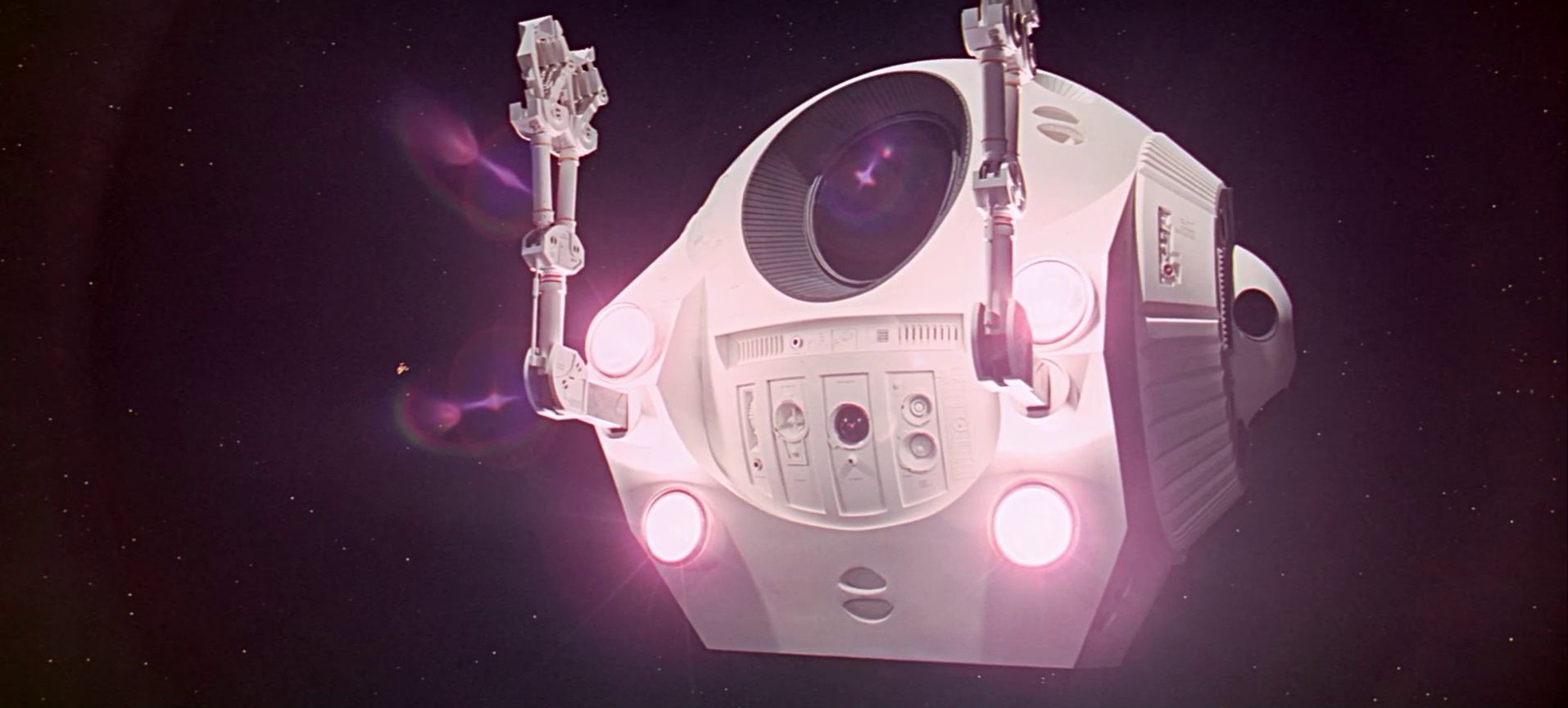
The last one, I am not completely sure about. But it seems that the Pods also feature a HAL eye.
So, to answer the question from the top: It seems that there are seven HAL 9000 faceplates in the movie, plus two additional HAL eyes.
If I missed anything, please let me know in the comments!