At a local Thrift Store, I found this VR headset for 50 cents.
What made this one special, is its transparent front plate. This inspired me to convert it into futuristic looking "Sci Fi goggles", based on a Arduino pro mini and with different blinking LEDs.
Materials:
the VR headset
Arduino Pro Mini (3.3V, Atmega168, 8MHz)
PCB 4cm x 6cm
Battery holder for 3 rechargeable AA batteries
two toggle switches
one momentary push button switch
10pcs red 5mm LEDs (the clear ones are the brightest)
10 holder clips for the 5mm LEDs
3pcs 3mm LEDs blue, green, orange
1 COB LED (cold white) 1W, 60mm x 8mm
a 2N2222 transistor
14 resistors and a 100nF capacitor
Step 1: "breaking" the VR headset
I disassembled the VR headset, and removed the optical lenses.
I drilled five holes in each, the left and the right side to fit the clips that hold the 5mm LEDs plus three holes on the right side for the two switches and the push button switch.
In the bottom of the front piece, I drilled three holes to fit the 3mm LEDs.
The center plate on the front is removed with a utility knife.
Step 2: the PCB
The 13 (5mm and 3mm) LEDs are directly connected to Arduino pins. This is fine with the Arduino's max. current as long as you make sure that not more than a few LEDs are turned on at the same time. The 1W COB LED is connected via a 2N2222 transistor.
The connectors for the Arduino pro mini, the resistors, and the 2N2222 transistor are soldered to a 6cm x 4cm PCB (which is small enough to be mounted at the vertical wall in the middle of the headset.
Step 3: the LEDs and switches
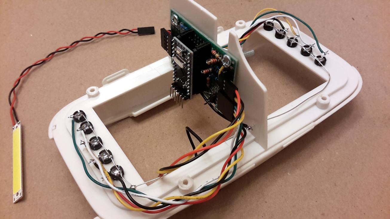
The clear red 5mm LEDs are mounted with their clips and on each side their cathodes are soldered to a 5-pin cable. The anodes of all 10 LEDs are connected.
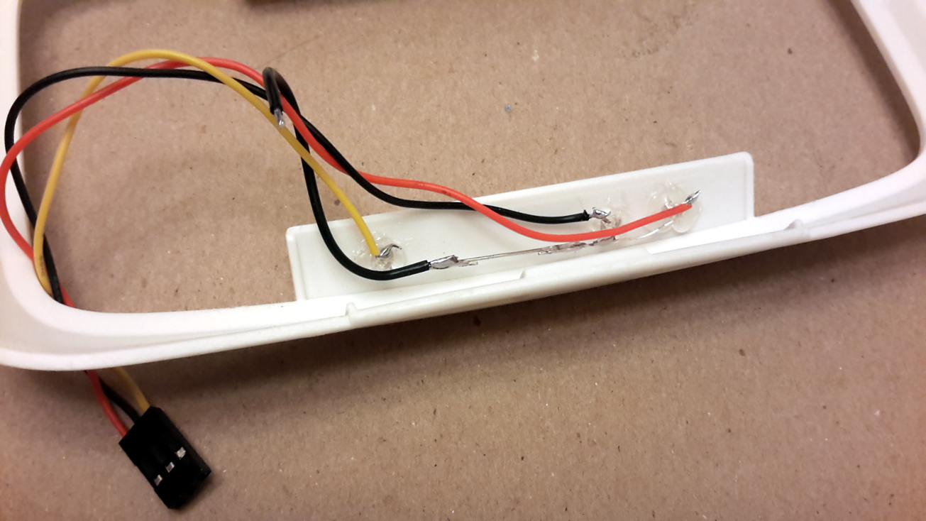
The three 3mm LEDs are hot-glued to the three bottom holes. Again, the catodes are soldered to a 3-pin cable, and their anodes are connected.
The three switches and the COD LED are also soldered to connector cables.
And everything is mounted to the headset.
Step 4: The Arduino Code and Operation
The Arduino code is basically the big brother of the "blink without delay" example sketch. The toggle switch at the front turns on the power. With the power is turned on, the two vertical rows with 5 red LEDs each are displaying different patterns. They may either only go up, or only down, or up and down in synch, or opposed to each other - or in a random walk. The three 3mm LEDs at the bottom blink randomly in 3-5 second intervals such that typically two (out of the three) LEDs are on.
The second toggle switch turns on a random flickering of the (very bright) cold white 1W COB LED at the top. In this mode, the momentary push button switch turns on a strobe effect of the COB LED.
That's it.
At night, these "Sci-Fi glasses" are a wonderful effect. They go nicely together with a "weird scientist" costume or, in my case, my Doc Brown outfit.
While building the Time Circuits from "Back to the Future", I needed lots of Arduino pins for the nine 4-digit 7-segment displays, plus more pins for some LEDs, three serial connections (two for communication with other devices and one for sound). Therefore I decided to spend a few thoughts on how to reduce the number of pins required for the 3x4 keypad, plus the additional white button (bottom, left in the picture).
The principle
The solution, in two words is: "voltage divider". The principle of the voltage divider is indicated here:
The output voltage (Vout) is a certain fraction of the input voltage (VCC) that is defined by he ratio of the two resistors R1 and R2. If R2 is much larger than R1, then Vout will be close to VCC. If R2 is much smaller than R1, Vout will be close to zero. And if R1 = R2, then Vout = VCC/2.
Example: 2 switches
Let's start with an example where two switches are connected to a single analog input. In the sketch below we assume that R1 = R2 (maybe 3k - the exact value does not matter, only their ratio).
The middle pin is connected to an Arduino analog input. When both switches S1 and S2 are open, the following line
val = analogRead(A1);
returns a value of val=0 (as the input is connected to GND, via R2). When S1 is pressed (and the input is connected to VCC), it returns val=1023. When S2 is pressed (and the input is at VCC/2), it returns val=512. Notice: all these analog values are approximate. The values may slightly fluctuate with time, with temperature, etc. In this circuit I would simply check if val<250 (indicating that no button is pressed, or 250<val<750 (S2 is pressed), or val>750 (S1 is pressed). Please notice that this circuit cannot distinguish whether both S1 and S2 or only S1 are closed.
Another example: 3 switches
The principle should now be clear, so let's extend the circuit to three switches.
I would pick R1=R2=R3 (maybe between 1k and 3k, but all the same). Then we get the following analog readouts: 0 (no switch), 341 (S3 closed), 518 (S2 closed), or 1023 (S1 closed). Again, with this circuit one cannot identify simultaneous button pushes.
The keypad circuit
Now that the basic idea is clear, let's extend this to the matrix of a 3x4 keypad using a set of 1k and 3k resistors as indicated in the image below. The fractions of the supply voltage VCC, as seen at the output pin ("analog in") are as listed in the table. It is also possible to add additional push buttons, as indicated by the piece below the dashed line.
One restriction of this circuit is that it will only work if only one button is pushed at a time. With a little thought, one might be able to select the resistors such that one could identify multiple button presses at a time - but this was beyond the scope for this project.
Arduino code
The output ("analog in") is directly connected to one of the Arduino analog inputs, e.g. A1. The code then reads this input with
value = analogRead(A1);
The readout will give values between 0 (if A1 is connected to GND) and 1023 (if A1 is connected to VCC). One has to take into account, that the readout values may vary a little (over time, maybe with temperature). The most robust approach is to press all the keys (one by one) and note the corresponding readout values. Then create a list of boundaries which are safely in between these values. For example, if the readout values were 190, 215, 236, 255 (which may vary by plus-minus one or two), I would pick boundaries of 202, 227, 245. The code would then simply check between which boundary values the readout value is. Example code where the result is stored in the "key" variable (key=99 means that no button was pressed):
  value = analogRead(A1);
  if (value < 150) {
    key = 99;
  } else if (value < 202) { key = 13;
  } else if (value < 227) { key = 3;
  } else if (value < 245) { key = 1;
    ...
  } else { key = 5;
  }
After many years I had watched “Back to the Future” again. No comment needed! But this time, I saw it with very different eyes. And when I saw the flux capacitor, I knew that I wanted one. The electronics will be based on an Arduino (the Arduino Pro Mini which is small and cheap - which I am using in most of my projects), so the main challenge will be on the mechanical side. I am always building things on a budget. So, I am not aiming at 100% accuracy. I just want to get the main features right and, like with my HAL 9000 replica, most people will not be able to tell the difference from the real thing – only a few experts/nerds will be able to do that.
In the first step, I collected information. Here are links that were helpful and inspiring:
The enclosure used for the original prop is a fiberglass electrical enclosure box Stahlin J1210HPL. This can still be bought on eBay (usually versions without the front window). However, it sells typically for more than $100 which is beyond what I plan to pay for the whole device. Like in one of the links, I will build this from wood. Somewhere (I forgot where…), I found the precise measures for the box – here they are:
Parts and Pieces
After some research and viewing other people’s builds, this is the list of all the parts that I will use, separated into three categories: enclosure, inner pieces, electronics.
Enclosure
The original movie prop is using the Stahlin J1210HPL industrial enclosure. It measures 12″ H x 6″ D x 10″ W. They sell some of these on Ebay, but they are quite expensive. Furthermore, they usually do not offer the versions with the window, so you would have to add additional work. I decide to build the enclosure from wood. Recently, I got access to a laser cutter, and this is how I’m gonna do it. I will make the .dxf files for the laser cutter in the open source software librecad (for Windows, Apple, and Linux). The enclosure is build from 3/16″ (5mm) plywood. The window is made from 3/32 acrylics, and I get the gasket from Amazon. For the metal pipes on the right and the top, I am using 1 1/2″ PVC elbows.
Inside & Details
The round metal disks in the original movie prop used old electrical vacuum solenoids which are not available anymore (maybe as collectors items). Like some other people, I am using the metal piece from these electrical plugs.
Next to the metal disks come three 3/8″ acrylic blocks, on top of which I place 12mm plastic tubes in which I place 12 gauge copper wire.
Electronics
The following pieces are used
Arduino Pro Mini (ATmega 168, 16MHz, 5V)
DFPlayer mini module
128MB microSD card
3W 40mm speaker
12 warm white 5mm LEDs (for the Y-pattern below the acrylic blocks)
1 white 8mm 0.5W straw hat LED (in the center)
8 5mm (cold) white straw hat LEDs for the sides of the enclosure (straw hat LEDs have a more even light distribution pattern)
DFPlayer Mini module
128MB micro SD card
40mm 3W speaker
2N3904 and 2N2222 transistors, various resistors
power switch, two momentary switches (to set modes, and sound options)
PIR module (infrared motion sensor)
2.1mm power socket
USB to 2.1mm power cable
Other
Embossing Label Maker DYMO 1540 Office Mate II and red tape for the three labels. (note: other label makers may not have the correct font)
Spray paint: glossy medium gray (enclosure), satin black (inner board), almond (sides of the acrylic blocks), silver (PCV elbows)
Laser Cutter & Paint
The construction of this Flux Capacitor makes heavy use of a Laser Cutter. The pieces for the enclosure are cut from 3/16″ plywood.
The enclosure is glued, and the edge of the front window is sanded down, to fit the window gasket.
Then the thin frame is glued to the front window, and the switchplate into the enclosure.
The acrylic blocks are cut out of a 3/8″ acrylic board. The outer edge is masked with masking tape and the sides are sprayed with almond paint.
Then the PVC elbows and the spacers for the metal disks are painted in aluminum.
The enclosure and the front plate are spray painted in dark gray. Then the gasket is inserted into the front window, and a thin (3/32″) piece of acrylic is mounted behind.
The labels from the Dymo 1540 Office Mate are then glued to the front side.
The Inside
The top side of the inner board of the Flux Capacitor is holding the acrylic blocks, and the solenoids.
The inner board is painted matte black. For this build I replaced the (expensive!) solenoids with (cheap!) metal bases of electrical power plugs. I inserted a wooden dowel which then holds a red spark plug cap with the yellow Ethernet cable inserted.
The metal pieces are screwed to silver painted wooden spacers on the board.
The acrylic blocks are glued to the board. Pieces of copper wire are fed through a hole in the power plugs, and inserted into 12mm plastic tubes.
Electronics
The electronics is mounted to the bottom side of the inner board. These consist of an Arduino Pro Mini (168, 16MHz, 5V), warm white clear LEDs (below the acrylic blocks), cold white straw head LEDs (at the sides of the board, they flash when the baby hits 88 mph), the DFPlayer mini module which plays .mp3 sounds from a 128MB (yes "MB", they still make these!) microSD card.
The LEDs that sit below the acrylic blocks are soldered onto three PCBs which are screwed onto the wood.
Here is a sketch how these are connected
The straw hat LEDs and the 3W speaker are hot-glued onto the board. The PCB holding the Arduino Pro Mini and the DFPlayer module is added, and everything is connected by cables. I have described the DFPlayer module in an earlier blog entry.
Here is a sketch of the circuit on the main PCB.
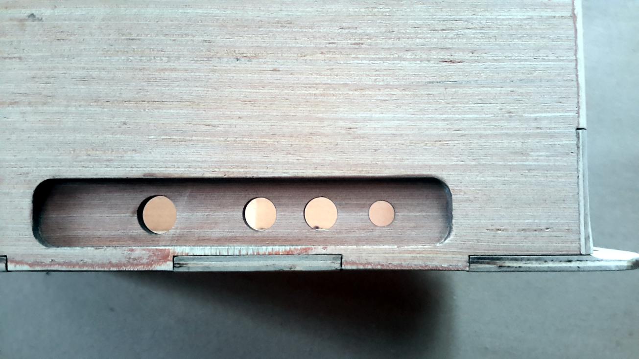
The four openings on the left side of the Flux Capacitor enclosure are holding (from top to bottom): the power switch, two momentary push buttons (for mode of operation and sound volume), and a 2.1mm socket for the USB-to-2.1mm) power cord.
Software
The software is written in the Arduino IDE. I always find it important for a prop like this not to become boring due to a behavior that is too predictable. That's why I always spend some time to come up with a variety of light and/or sound patterns. With short breaks, the Flux Capacitor continues to run randomly one out of five different patterns for the Y-shaped LED bars in the center. After a certain time, it will run a "full power" pattern, which also enables the cold-white LEDs at the edges of the board. This pattern corresponds to reaching 88mph (when something serious happens). The Flux Capacitor operates in four different "activity modes", in which the"full power" patterns occur approx. every 66sec (mode #4), 2 1/2min, 6min, or never (mode #1).
The "full power" operation is accompanied by longer, aggressive electrostatic sparking sounds, while in the regular modes only rarely some softer electro-buzz is heard. The volume can be set to four different levels.
The PIR motion sensor that is built into the bottom of the enclosure is actually not used. Initially, I liked the idea, but ultimately I did not see the point.
When the Flux Capacitor is turned on, the famous Back-to-the-Future "Twinkle" sound is playing. And there is one easter egg: when both the volume and the mode buttons are held during turn-on, it plays the sound clip from Doc Brown: "When this baby hits 88 miles per hour, you're gonna see..."
That's it: this is my Flux Capacitor and I love it! Most people recognize it, and everybody likes it. Once, I took it to a screening of BTTF part I and one kid asked me if it really works - the little boy was not talking about the lights - he was referring to time travel... The most frequent question I get asked is: "Where is your Delorean?" Well, I guess this Flux Capacitor will have to settle to traveling in an boring Toyota...
Source Files
The files for this project (laser cutter, Arduino code, and sound clips) are stored at GitHub.