Showing posts with label Flux Capacitor. Show all posts

Wednesday, March 10, 2021

LilyGo T-Watch 2020 goes Back to The Future


The LilyGo T-Watch 2020 hit the market in May 2020. A programmable watch with reasonably small size (looking somehow like the Apple watch), based on the ESP32 processor with an accelerometer, plus Wifi and Bluetooth connectivity at a price of only $30-$40.

When I bought mine in December 2020, I thought I was already late to the party. But then, I started to search the web for great watch faces for the T_Watch and I did not find much. So, I decided to make my own, and share this. Being a fan of the "Back to the Future" trilogy, in which the topic of "time" is omnipresent, I decided to make a Back-to-the-Future fun watch - and to share this.

This watch is not a smart watch! It does neither use the Wifi nor Bluetooth connectivity of the watch (I wouldn't know what I would use this for anyway). This watch will just be fun to look at, and without WiFi and Bluetooth, but with a good power management, the watch will be able to run three or four days without charging.

T-Watch 2020 with Back-to-the-Future Time Circuits watch face

Setting up the programming environment

The very first step is to install and set up the Arduino IDE. I have described this in detail in another blog post: Lilygo TTGO T-Watch 2020: Getting Started / The Software Framework.


References

While I did not find many great watches, I found plenty of good information and example codes that helped me to understand specific details of the watch. The power management, in particular, is very important, in order to get a watch that does not have to be charged every day. Here I'm listing some references that were valuable and from which I benefited a lot when writing my code.

  • The SimpleWatch example that comes with the TTGO T-Watch library
  • A series of articles at diyprojects.io (also check the links to their other articles)
  • The code for "aGoodWatch" from Alex Goodyear
  • The article and code at instructables.com by Dan Geiger
  • An interesting "Wordclock" by instructable.com user ArduinoAndy

Requirements

As mentioned above, I wanted this to be a fun watch that can be used in every day life, which means that it needs a very efficient power management. Therefore, in this project I am not using the WiFi and Bluetooth which helps a lot to save power. It allows to reduce the CPU frequency of the watch (from nominal 80MHz out of a max of 240MHz) down to 30MHz. The graphics are all programmed using the TFT_eSPI library. In contrast to many common example codes that have tiny buttons in their settings menus, the Back-to-the-Future watch has large buttons which can easily accessed. 


Features

My Back-to-the-Future watch code features five different watchfaces, a stop watch, and a settings menu with four screens (two to customize the display, and two to set time and date). The different categories can be thought of as three rows: The middle one has the watch faces, to top one the stopwatch, and the bottom row the settings menu.
The watch can be in three states: 
  1.  Full operation with the display on 
  2.  After a few seconds of full operation, it turns to light sleep from which it can be quickly awakened. This is done either by a press on the button at the top right - a quick(!) double tap - or by rapidly moving the watch upwards and rotating it towards you.
  3. To save power (e.g. over night) the watch can be set to deep sleep, by pressing the button for 5 seconds. It takes another (approx. 2 sec) press of this button to wake it up, which takes about 5 seconds.
In a very bright environment, you can use a double tap on the screen to get the maximum screen brightness. The next time when the watch returns from light sleep, the brightness is back at the normal value.

Watchfaces

The watchfaces, include a fluxing flux capacitor, the time circuits (with the current date/time in the middle row, plus typical movie dates in the top/bottom rows), the speedometer plus the plutonium gauges, the SID spectrometer, and the entrance sign to the Mall (which randomly appears as either "Twin Pines Mall" or "Lone Pine Mall"). 


T-Watch 2020 with Back-to-the-Future watch faces

T-Watch 2020 with Back-to-the-Future watch faces

The user can cycle through those with horizontal swipes. There are three different modes of operation: Whenever the watch returns from light sleep it either presents you with a random face (a: random), the next face (b: cycle), or the same face that was displayed before it went to sleep (c: "fixed").

Stopwatch

If you swipe to the top row, you get the stopwatch, which is modeled after the one Doc Brown uses in his experiment with Einstein (except for the display color, since yellow is much brighter than red).


Menu with Settings

When, starting from the watchfaces, you swipe to the bottom row, you get an "entry" screen: "Enter the Settings - swipe" from which you can swipe into the settings. The additional entry screen prevents you from erroneously entering the actual settings and from unwanted changes of your setup.

Swiping to the right, you get to part one of the display settings where you can select 
  • how the watchfaces are diplayed (random, cycle, fixed - as described above) 
  • the format in which the time is displayed: 12h, 12h plus seconds, or 24h format
  • if the stepcounter is shown in the top left corner (on/off)
  • if the remaining battery percentage is dislayed in the top right corner (on/off) 


On part two of the display settings you can select
  • how long the watch stays on: 7 sec, 12 sec, or 20 sec (I prefer 7 sec which is long enough for me to read the time. I used 20 sec to make the video, without the watch turning off all the time. I also use the 20 sec setting if I just enjoy looking at the watch...)
  • three levels of brightness (low, med, high)
  • if you want the display to dim at night (between 10pm and 7am).
On the next two screens, you can set the time and date. Any changes that are made with the "+" and "-" buttons are only stored when the "SET TIME" and "SET DATE" buttons are pressed.  


Swiping to the row above brings you back to the watchfaces.

Installing the Code

The code can be obtained from my github repository https://github.com/mawob/bttfWatch.
From the green "Code" pulldown menu, select "Download ZiP"


Unzipping the file creates a folder "bttfWatch-main" which has all the relevant files. Rename the folder from "bttfWatch-main" to "bttfWatch" and move this into the Sketchbook folder of your Arduino IDE. Then open it from the File menu, connect your watch, upload, and enjoy your new watchface!


Monday, May 20, 2019

Brick Stage: Marty & Doc (Back to the Future)

When I got that tiny 0.96" LCD display with 80x160 pixels in my hands, I loved it and started looking for applications. Earlier, I had thought about building little wooden stages with different scenarios for some of my collected brick figures. So, why not bringing the two together and make a little stage for my Marty and Doc figures? Featuring the smallest functioning Flux Capacitor in the world?


Electronics and Code

The 0.96" LCD display is directly connected to an Arduino Pro Mini (ATMega328, 16MHz, 5V). Seven connections are needed in total (display-Arduino): GND-GND, VCC-VCC, SCL-D13, SDA-D11, RES-D7, DC-D8, CS-D9. No other hardware is required (of course, it never hurts to add a 100uF plus a 100nF capacitor between VCC and GND). 
The Arduino code is using the TFT_ST7735.h library which is available at https://github.com/Bodmer/TFT_ST7735 and nicely described by the author at https://forum.arduino.cc/index.php?topic=397984.0.


I decided to display three different screens with different pieces of the time machine's electronics: The first screen shows the flux capacitor and the SID (spectrum indicator display), the second screen shows the time circuits (the clock), and the the third screen shows the speedometer and the analog gauges. The time interval that each screen is displayed is chosen randomly between 40-70 seconds.

The Wooden Stage

The stage is made of 3/16" plywood using a laser cutter with an engraved picture of the DeLorean and the sketch of the Flux Capacitor ("After I fell from the toilet, I drew this!"). 


The LCD display is mounted from behind. The 5V supply voltage is connected on the right side with a 2.1mm DC power connector. The whole stage is 6" wide, 3 5/15" tall, and 3 11/16" deep.

Operation

The "Marty and Doc" stage in operation can be viewed in the YouTube video at the top.

Great Scott!

PS: Version without Electronics

I also made a second version of the Marty & Doc stage without any electronics

Related

My other blog posts on BTTF-related props and pieces:
   - Building a Flux Capacitor
   - Building the Time Circuits
   - Building a Hoverboard and Charger
   - Building BTTF clocks


Friday, December 14, 2018

Building a BTTF Flux Capacitor


Planning the build

After many years I had watched “Back to the Future” again. No comment needed! But this time, I saw it with very different eyes. And when I saw the flux capacitor, I knew that I wanted one. The electronics will be based on an Arduino (the Arduino Pro Mini which is small and cheap - which I am using in most of my projects), so the main challenge will be on the mechanical side. I am always building things on a budget. So, I am not aiming at 100% accuracy. I just want to get the main features right and, like with my HAL 9000 replica, most people will not be able to tell the difference from the real thing – only a few experts/nerds will be able to do that.
In the first step, I collected information. Here are links that were helpful and inspiring:
The enclosure used for the original prop is a fiberglass electrical enclosure box Stahlin J1210HPL. This can still be bought on eBay (usually versions without the front window). However, it sells typically for more than $100 which is beyond what I plan to pay for the whole device. Like in one of the links, I will build this from wood. Somewhere (I forgot where…), I found the precise measures for the box – here they are:
 

Parts and Pieces

After some research and viewing other people’s builds, this is the list of all the parts that I will use, separated into three categories: enclosure, inner pieces, electronics.

Enclosure

The original movie prop is using the Stahlin J1210HPL industrial enclosure. It measures 12″ H x 6″ D x 10″ W. They sell some of these on Ebay, but they are quite expensive. Furthermore, they usually do not offer the versions with the window, so you would have to add additional work. I decide to build the enclosure from wood. Recently, I got access to a laser cutter, and this is how I’m gonna do it. I will make the .dxf files for the laser cutter in the open source software librecad (for Windows, Apple, and Linux). The enclosure is build from 3/16″ (5mm) plywood. The window is made from 3/32 acrylics, and I get the gasket from Amazon. For the metal pipes on the right and the top, I am using 1 1/2″ PVC elbows.

Inside & Details

  • The round metal disks in the original movie prop used old electrical vacuum solenoids which are not available anymore (maybe as collectors items). Like some other people, I am using the metal piece from these electrical plugs.
  • On top of these come three red rubber spark plug boots, and the yellow cable is cheap Ethernet cable.
  • Next to the metal disks come three 3/8″ acrylic blocks, on top of which I place 12mm plastic tubes in which I place 12 gauge copper wire.

Electronics

The following pieces are used
  • Arduino Pro Mini (ATmega 168, 16MHz, 5V)
  • DFPlayer mini module
  • 128MB microSD card
  • 3W 40mm speaker
  • 12 warm white 5mm LEDs (for the Y-pattern below the acrylic blocks)
  • 1 white 8mm 0.5W straw hat LED (in the center)
  • 8 5mm (cold) white straw hat LEDs for the sides of the enclosure (straw hat LEDs have a more even light distribution pattern)
  • DFPlayer Mini module 
  • 128MB micro SD card
  • 40mm 3W speaker
  • 2N3904 and 2N2222 transistors, various resistors
  • power switch, two momentary switches (to set modes, and sound options)
  • PIR module (infrared motion sensor)
  • 2.1mm power socket
  • USB to 2.1mm power cable

Other

  • Embossing Label Maker DYMO 1540 Office Mate II and red tape for the three labels. (note: other label makers may not have the correct font)
  • Spray paint: glossy medium gray (enclosure), satin black (inner board), almond (sides of the acrylic blocks), silver (PCV elbows)

Laser Cutter & Paint

The construction of this Flux Capacitor makes heavy use of a Laser Cutter. The pieces for the enclosure are cut from 3/16″ plywood.


The enclosure is glued, and the edge of the front window is sanded down, to fit the window gasket.


Then the thin frame is glued to the front window, and the switchplate into the enclosure.


The acrylic blocks are cut out of a 3/8″ acrylic board. The outer edge is masked with masking tape and the sides are sprayed with almond paint.


Then the PVC elbows and the spacers for the metal disks are painted in aluminum.


The enclosure and the front plate are spray painted in dark gray. Then the gasket is inserted into the front window, and a thin (3/32″) piece of acrylic is mounted behind.


The labels from the Dymo 1540 Office Mate are then glued to the front side.

The Inside

The top side of the inner board of the Flux Capacitor is holding the acrylic blocks, and the solenoids.


The inner board is painted matte black. For this build I replaced the (expensive!) solenoids with (cheap!) metal bases of electrical power plugs. I inserted a wooden dowel which then holds a red spark plug cap with the yellow Ethernet cable inserted.


The metal pieces are screwed to silver painted wooden spacers on the board.


The acrylic blocks are glued to the board. Pieces of copper wire are fed through a hole in the power plugs, and inserted into 12mm plastic tubes.


Electronics

The electronics is mounted to the bottom side of the inner board. These consist of an Arduino Pro Mini (168, 16MHz, 5V), warm white clear LEDs (below the acrylic blocks), cold white straw head LEDs (at the sides of the board, they flash when the baby hits 88 mph), the DFPlayer mini module which plays .mp3 sounds from a 128MB (yes "MB", they still make these!) microSD card.


The LEDs that sit below the acrylic blocks are soldered onto three PCBs which are screwed onto the wood.


Here is a sketch how these are connected


The straw hat LEDs and the 3W speaker are hot-glued onto the board. The PCB holding the Arduino Pro Mini and the DFPlayer module is added, and everything is connected by cables. I have described the DFPlayer module in an earlier blog entry.


Here is a sketch of the circuit on the main PCB.


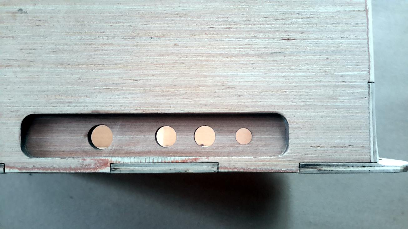
The four openings on the left side of the Flux Capacitor enclosure are holding (from top to bottom): the power switch, two momentary push buttons (for mode of operation and sound volume), and a 2.1mm socket for the USB-to-2.1mm) power cord.

Software

The software is written in the Arduino IDE. I always find it important for a prop like this not to become boring due to a behavior that is too predictable. That's why I always spend some time to come up with a variety of light and/or sound patterns. With short breaks, the Flux Capacitor continues to run randomly one out of five different patterns for the Y-shaped LED bars in the center. After a certain time, it will run a "full power" pattern, which also enables the cold-white LEDs at the edges of the board. This pattern corresponds to reaching 88mph (when something serious happens). The Flux Capacitor operates in four different "activity modes", in which the"full power" patterns occur approx. every 66sec (mode #4), 2 1/2min, 6min, or never (mode #1).
The "full power" operation is accompanied by longer, aggressive electrostatic sparking sounds, while in the regular modes only rarely some softer electro-buzz is heard. The volume can be set to four different levels.
The PIR motion sensor that is built into the bottom of the enclosure is actually not used. Initially, I liked the idea, but ultimately I did not see the point.
When the Flux Capacitor is turned on, the famous Back-to-the-Future "Twinkle" sound is playing. And there is one easter egg: when both the volume and the mode buttons are held during turn-on, it plays the sound clip from Doc Brown: "When this baby hits 88 miles per hour, you're gonna see..."


That's it: this is my Flux Capacitor and I love it! Most people recognize it, and everybody likes it. Once, I took it to a screening of BTTF part I and one kid asked me if it really works - the little boy was not talking about the lights - he was referring to time travel...  The most frequent question I get asked is: "Where is your Delorean?" Well, I guess this Flux Capacitor will have to settle to traveling in an boring Toyota...

Source Files

The files for this project (laser cutter, Arduino code, and sound clips) are stored at GitHub.


Related

My other blog posts on BTTF-related props and pieces:
   - Building the Time Circuits
   - Building the Speedometer
   - Building the Analog Gauges
   - Building the TFC Switch
   - Building a Hoverboard and Charger
   - Building BTTF clocks
   - Building a BTTF Brick Stage (featuring the smallest Flux Capacitor)